Lab 2
Set up the IMU
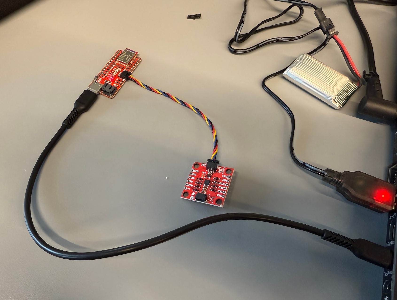
After downloading the “SparkFun 9DOF IMU Breakout_ICM 20948_Arduino Library” from the Arduino Library Manager, I connected the IMU to the Artemis board using the QWIIC connectors.
I ran the Example1_Basics code, and the video shows the accelerometer and gyro values changing as I rotate the IMU in different directions.
When the board is upright with Z up, the third accelerometer value is positive. When the board is Z down, this value becomes negative. I was also rotating the board about the X-axis, which is represented by the change in the first gyro value. Rolling the board such that X is up make the first accelerometer value positive, negative when X is down. Whether these values are positive or negative depends on the sign convention defined by the diagram on the IMU.
The AD0_VAL should be set to 1. The value becomes 0 when the ADR jumper on the IMU is closed. Since there is no jumper, the value should be 1.
I also added code in void setup() for the board to blink the LED three times when it powers on.
Accelerometer
The following code snippet shows the equations used to calculate pitch and roll:
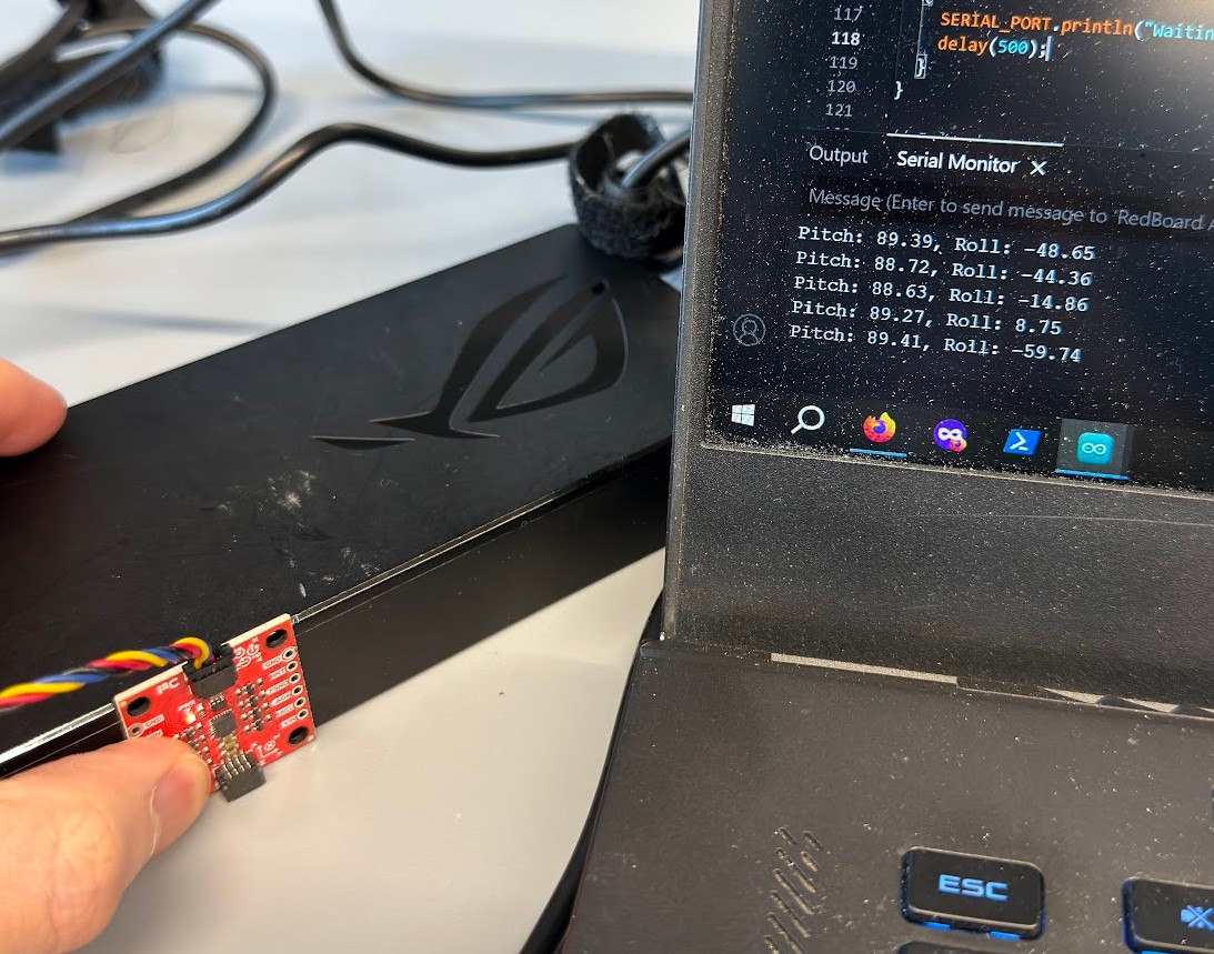
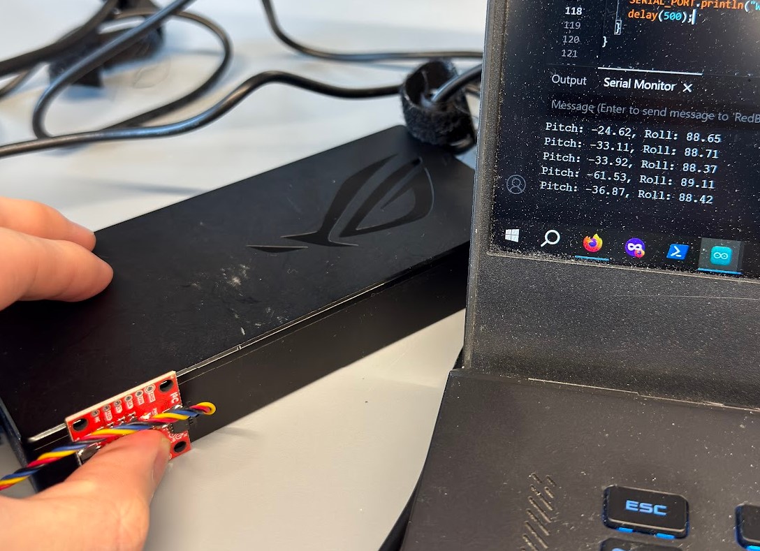
Pitch: 90 degrees
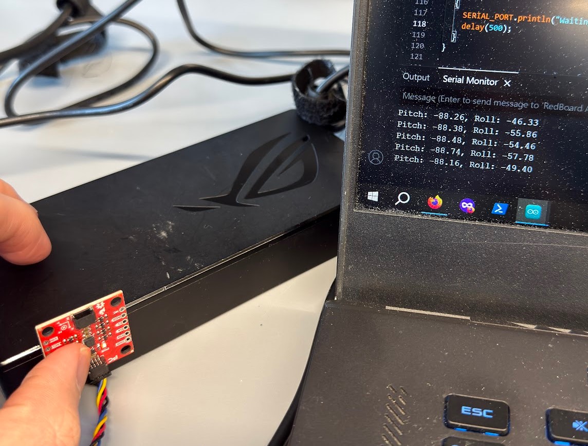
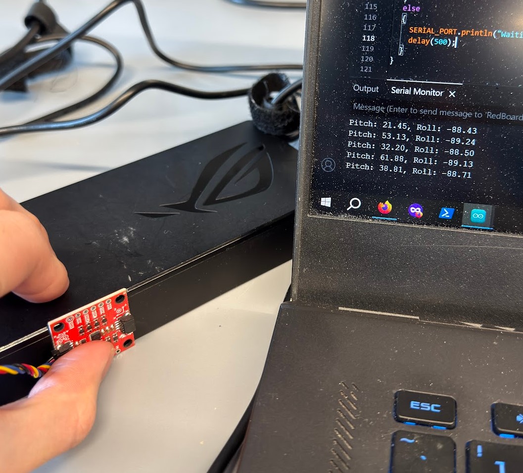
Pitch: -90 degrees
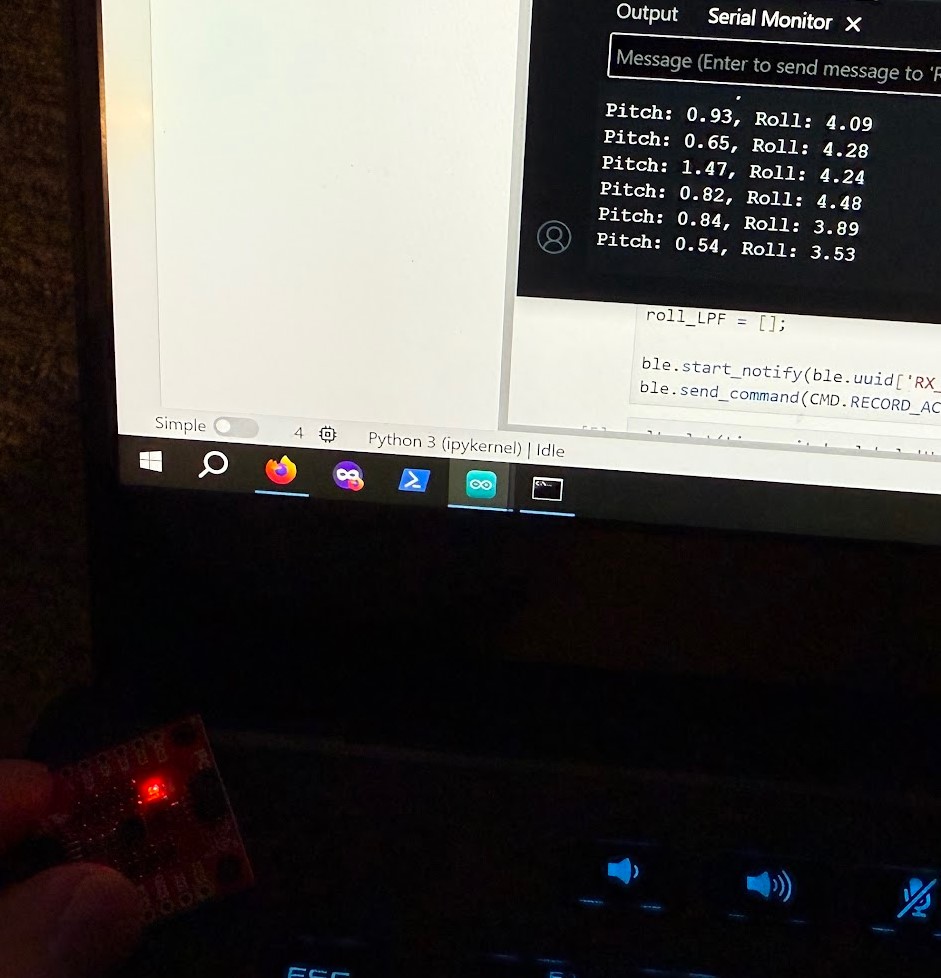
Pitch: 0 degrees and Roll: 0 degrees
Roll: 90 degrees
Roll: -90 degrees
I wrote a function in Jupyter to plot the data and time on a graph.
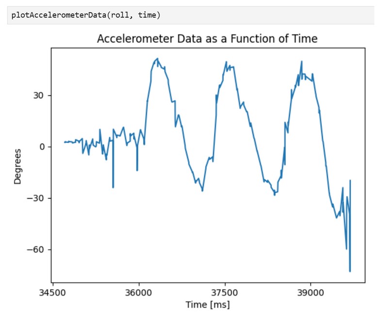
When the IMU is rolled and pitched to either 90 or -90 degrees, the output is off by one or two degrees.
For pitch, the average output is 89.084 degrees at the expected value of 90 degrees, the average output is -88.404 degrees at the expected value of -90 degrees. The calibration formula should be Corrected = (180 / 177.488) × Raw + (90 – (180 / 177.488) × 89.084)
For roll, the average output is 88.652 degrees at the expected value of 90 degrees, the average output is -88.802 degrees at the expected value of -90 degrees. The calibration formula should be Corrected = (180 / 177.454) × Raw + (90 – (180 / 177.454) × 88.652)
The following code performs a Fourier Transfrom of the data.
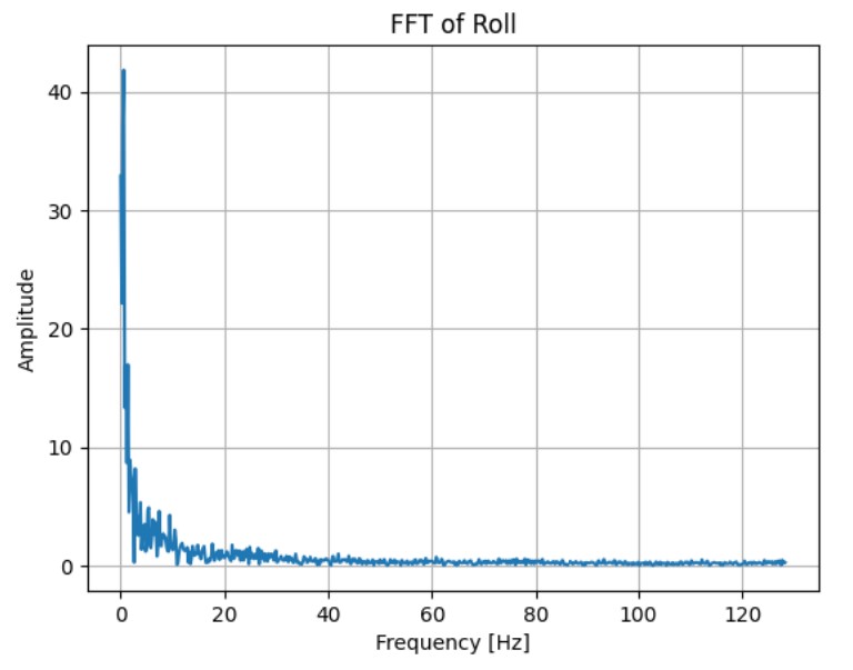
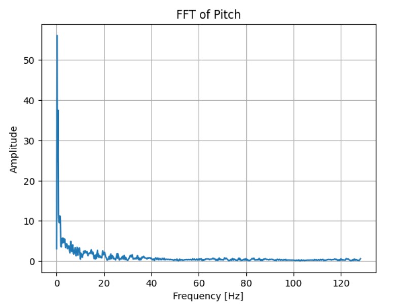
A high cutoff frequency leaves in more noise in the signal/data, while a low cutoff noise can smooth the signal too much and distort the original signal.
Let’s set the cutoff frequency (f_c) to 5 Hz. With f_c = 1 / (2πRC), RC = 0.03183. From the graphs, T = 0.003893, so alpha = T / (T + RC) = 0.10897.
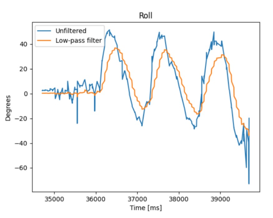
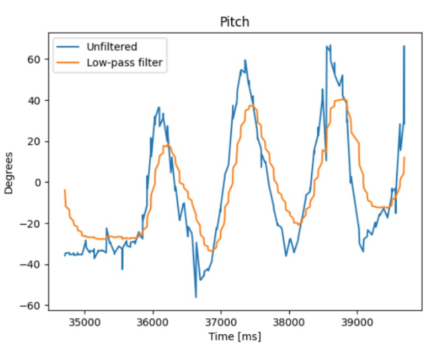
The low-pass filter smooths the signal and removes most of the high-frequency noise.
Gyroscope
The following code calculates the pitch, roll, and yaw of the IMU based on the gyroscope. dt is in milliseconds and is calculated as the time between the current and last loop time. The initial reading starts at 0, so the angles are relative, not absolute.
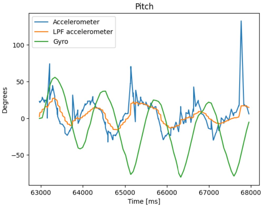
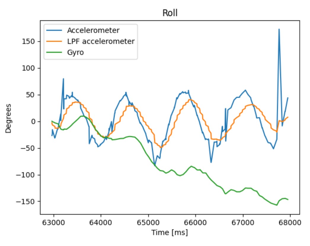
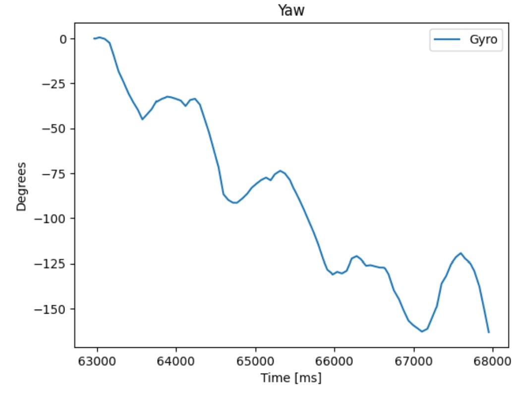
The gyro has significant drift. I was rotating and turning the IMU multiple times, which can explain the large error between the gyro and accelerometer readings. Also, the gyro reading starts at 0, which explains the vertical offset between the readings.
For the complementary filter, I used an alpha of 0.75 to rely more on the filtered accelerometer values rather than the gyroscope because of the gyro is easily affected by drift. A lower alpha would rely more on the gyro.
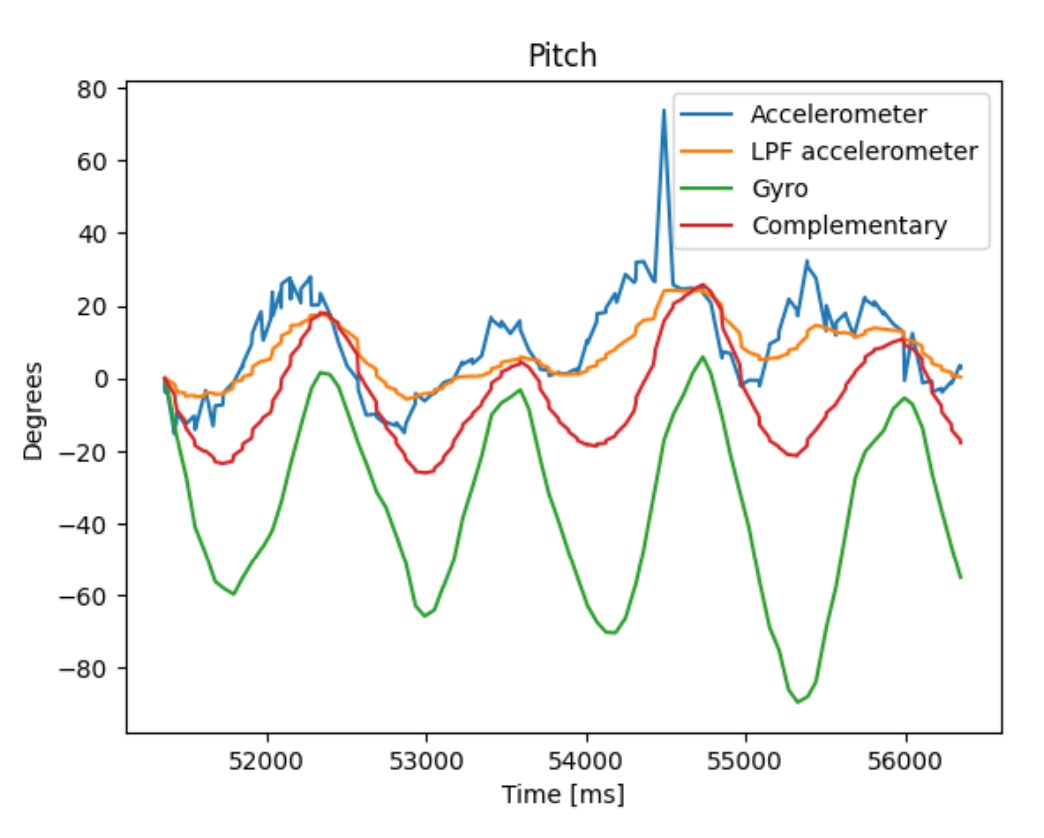
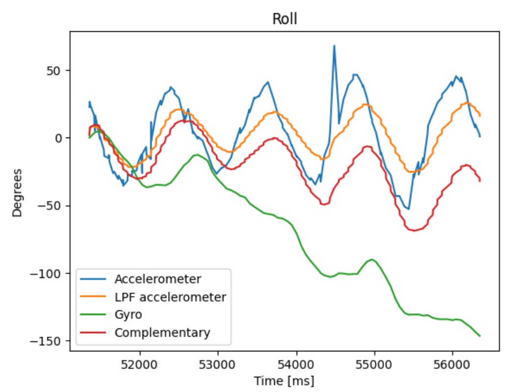
For pitch, the complementary filter values appear to be closer to the filtered accelerometer values than the gyro values. For roll, it appears that the complementary filter values are still affected by the gyro’s drift but to a lesser extent than just gyro alone.
Sample Data
I did not use if(myICM.dataReady()) in my code. Instead, I just used myICM.getAGMT(). There are no Serial.print statements in my code. The following code calculates and collects the pitch and roll values from the accelerometer and gyroscope along with the timestamps. I created 5 individual arrays to store these values. This makes it easier to access element i of each list using the same index number. This ensures all of the data corresponds to the same timestamp. Because there is math during the calculations of the values, it is best to set the data type of each array as a float. I set the array length to 10,000 to ensure that the array does not become full, and I collected the data for 5 seconds.
Over 5 seconds, the Artemis sent 2023 messages in the format of: Time [ms]: 263489.000 | Pitch (Filtered Accel): -11.792 | Roll (Filtered Accel): -0.099 | Pitch (Gyro): -4.568 | Roll (Gyro): 1.702. This message is 131 bytes long, which means the board sent 53,002.6 bytes/second. It appears that each message has unique values, so the Artemis is not running faster than the IMU can produce new values. With a speed of roughly 53 kB/s and a RAM of 384 kB, the Artemis can store about 7.25 seconds of data.
The first message is Time [ms]: 258490.000 | Pitch (Filtered Accel): -1.954 | Roll (Filtered Accel): -0.109 | Pitch (Gyro): -0.000 | Roll (Gyro): -0.000
The last message is Time [ms]: 263489.000 | Pitch (Filtered Accel): -11.792 | Roll (Filtered Accel): -0.099 | Pitch (Gyro): -4.568 | Roll (Gyro): 1.702
Record a Stunt
The car accelerates and turns very quickly. A quick acceleration forward and then a quick acceleration in reverse would cause the car to flip. Holding down left and forward at the same time makes the car turn about one of the tires instead of the center of the car. Towards the end of the video, I lost control of the car.
Collaborators
I collaborated with Sam Zhen while working on this lab.
Back to Labs