Lab 3
Prelab
According to the provided datasheet of the VL53L1X sensor and the product description on Pololu’s website, the sensor uses a I2C sensor address of 0x52 with a default 7-bit slave address of 0101001b.
It is ideal to retrieve distance data from both ToF sensors at the same time. Because both ToF sensors have the same hardwired address, I would need to power only one of the sensors by disabling the second sensor with its shutdown pin. I would then programmatically change the address of the first sensor and then re-enable the second sensor so that the two sensors would have different addresses. I would need to solder a wire between one of the sensor’s XSHUT pins to an GPIO pin on the Artemis. The other approach of continuously enabling and disabling the two sensors using their shutdown pins is not ideal since you can only get distance data from one sensor at a time.
I want to place the ToF sensors on the robot such that one sensor is placed on the front of the car and the other sensor is placed on the right side of the car. This would provide distance data in the X- and Y-directions relative to the car. Because the sensor’s field of view is 27 degrees, there are scenarios where the car may not be able to detect an obstacle. If there is an obstacle to the front left or front right of the car, the obstacle may be in the blindspot of the sensors and the car may collide with it.
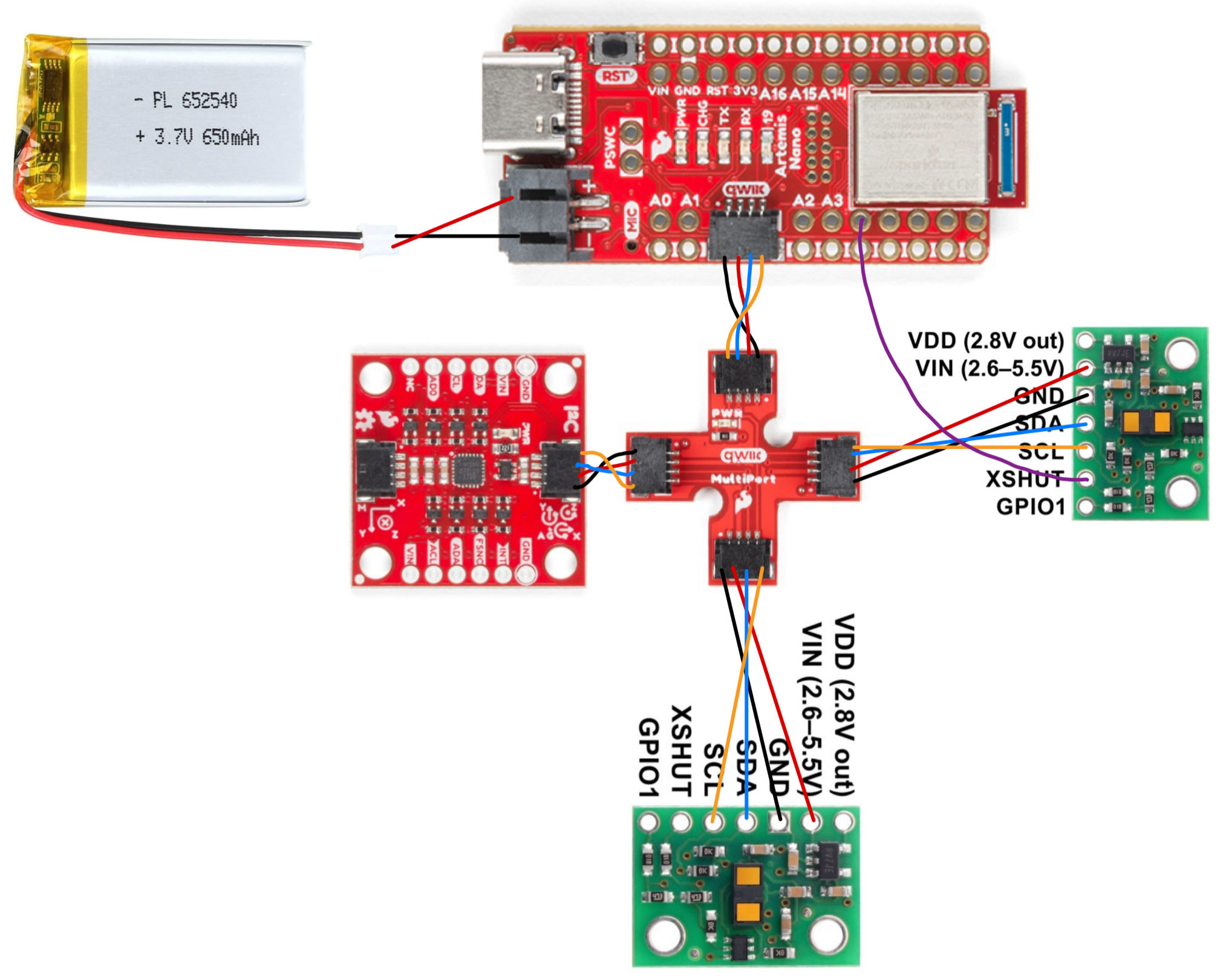
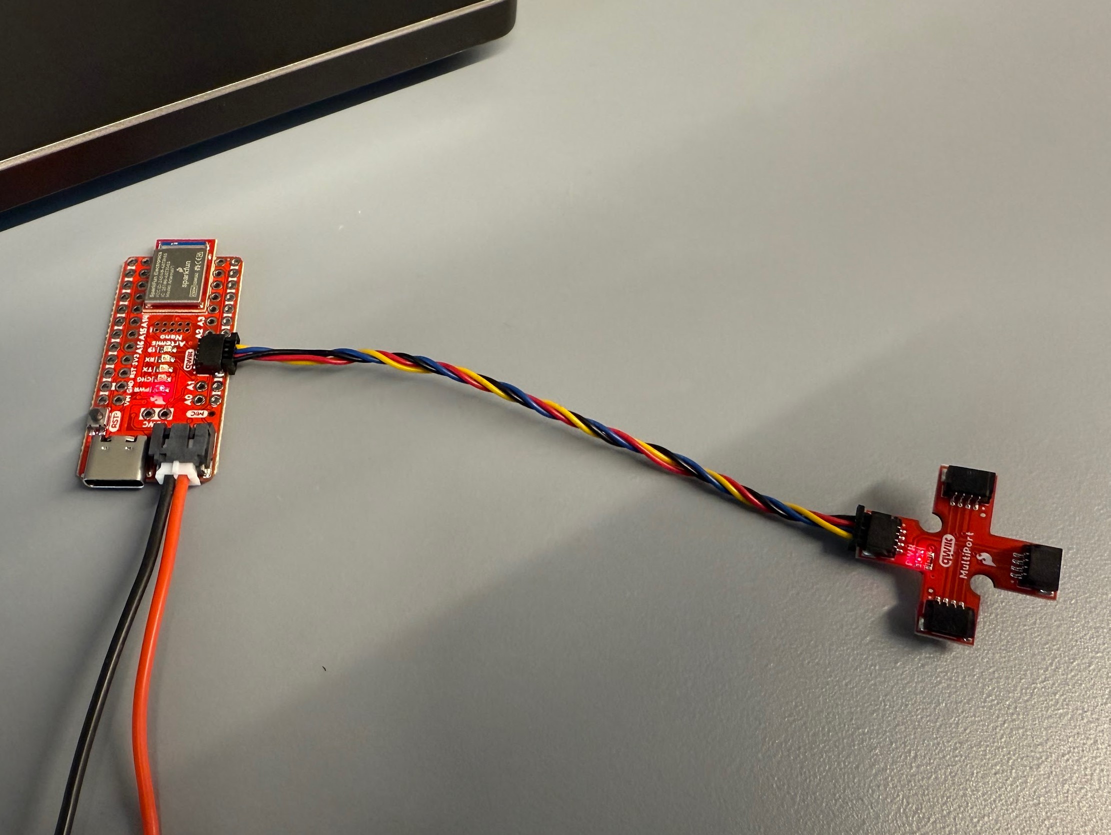
The battery with a soldered JST connector is connected to the power port of the Artemis board. A short Qwiic connector is connected from the Artemis to the breakout board. A short connector is connected from the breakout board to the IMU. The two long connectors are soldered to the ToF sensors. The black wire is soldered to GND, red wire to VIN, blue to SDA, and yellow to SCL. A wire is soldered from the XSHUT pin of one of the ToF sensors to an GPIO pin on the Artemis. The wires for the ToF sensors are soldered such that they are extending from the opposite side of where the sensor is, so the wires are not in the way of the sensor.
Task 1: Battery
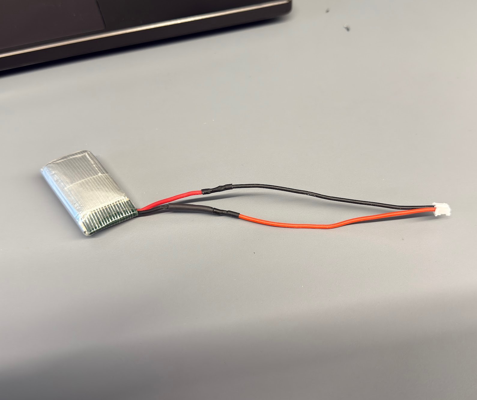
The wires on the battery are cut one at a time to ensure that the wires do not touch and cause a short circuit. The red wire of the battery is soldered to the black lead of the JST connector and the black wire to the red lead so that the polarity is correct when the battery is connected to the Artemis. Heat shrink is used to insulate the soldered connections.
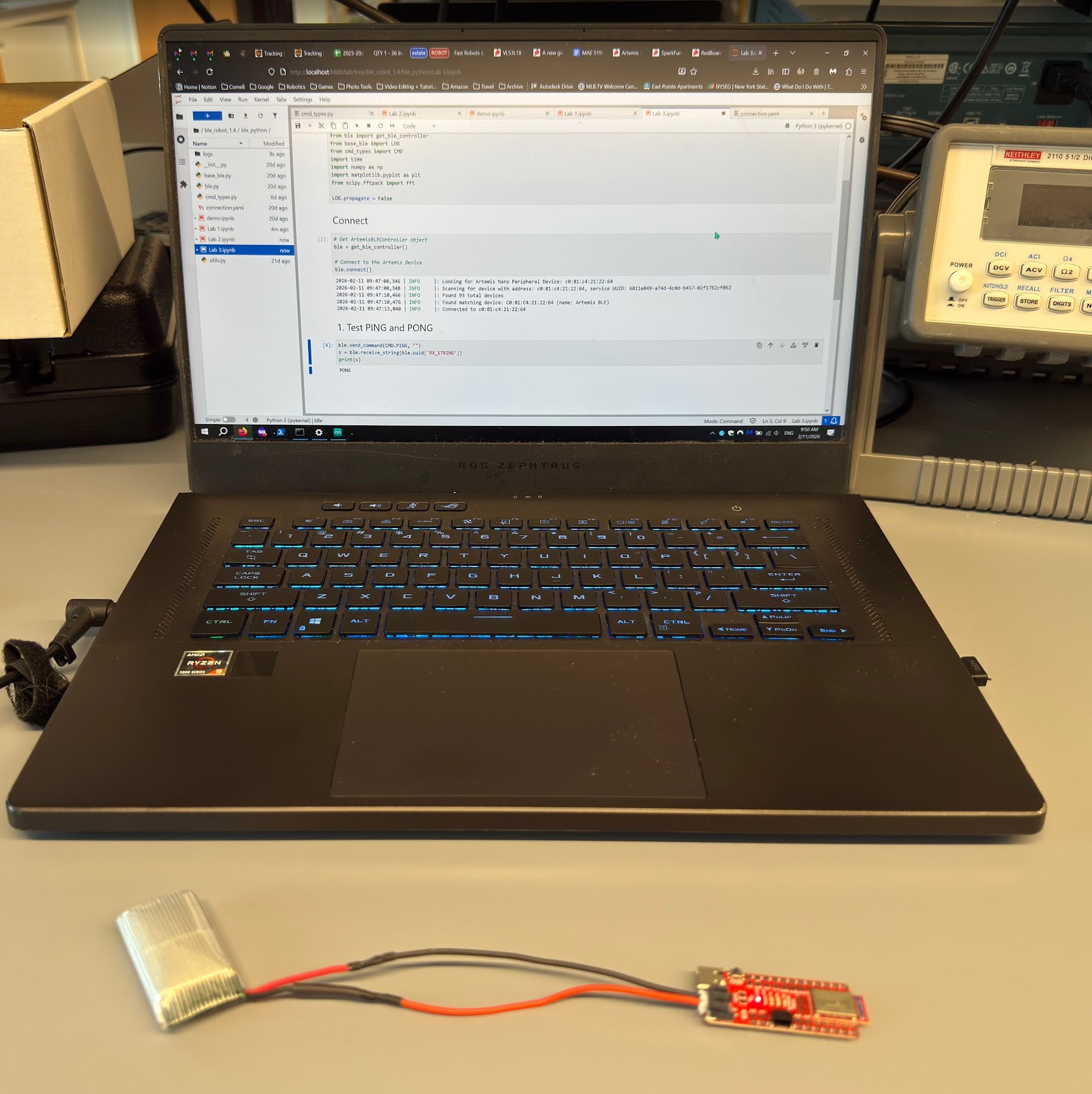
After connecting the battery to the Artemis, I tested PING and PONG to check that the Artemis is powered on correctly and can receive and send messages over Bluetooth with no physical connection to the laptop.
Task 2: Install Arduino library
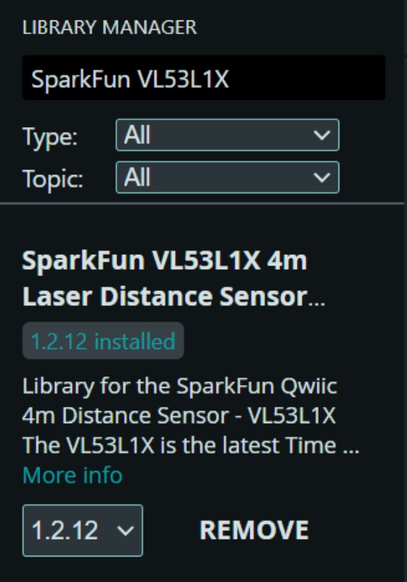
I installed the SparkFun VL53L1X 4m laser distance sensor library on my laptop.
Task 3: Connect the QWIIC break-out board to the Artemis
Task 4: First ToF sensor
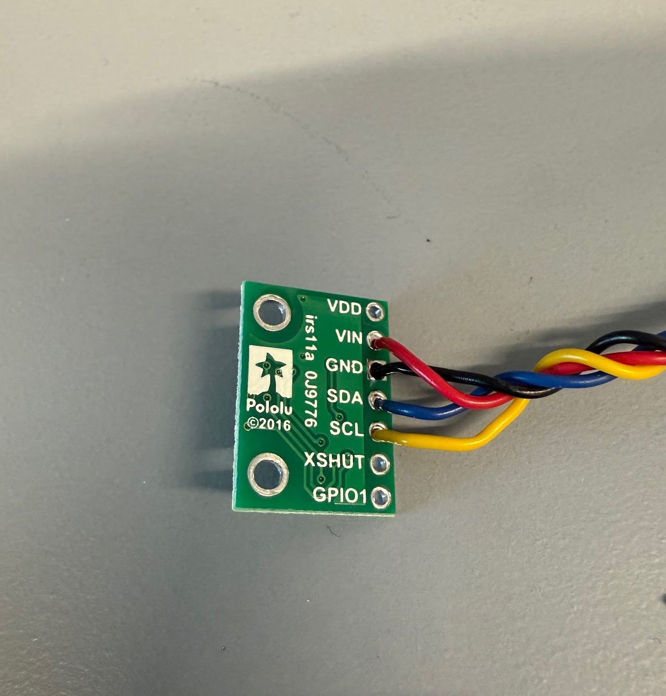
I cut one end of the long QWIIC connector to solder to the first ToF sensor. The black wire is soldered to GND, red wire to VIN, blue wire to SDA, and yellow wire to SCL.
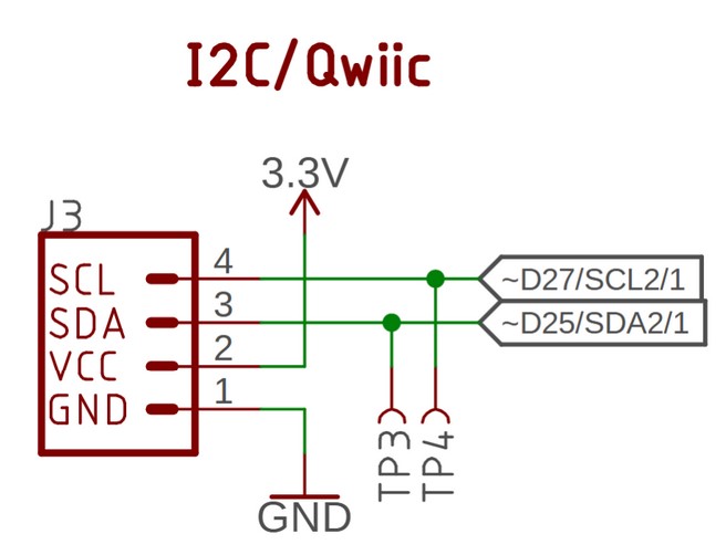
I used the above diagram to help me determine which color wires to connect to the pins of the ToF sensor.
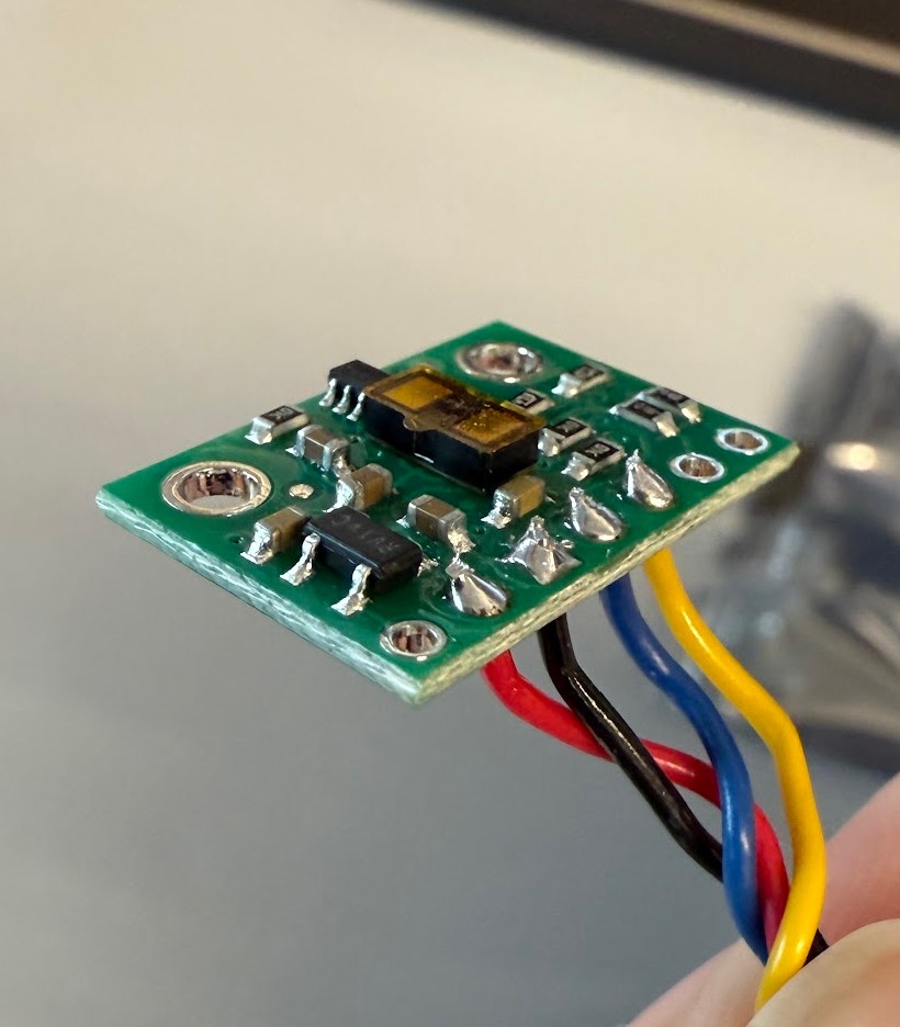
Make sure to snip the excess wire so it doesn’t short to each other.
Task 5: Scan the I2C channel
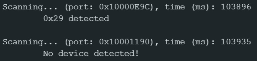
When running the Example05_wire_I2C example, the above screenshot shows that device 0x29 was detected on port 0x10000E9C. This does not match the expected address of 0x52 from the datasheet. This is because the I2C protocol uses a 7-bit address. The 7-bit address (as defined in Pololu’s product description) is 0101001 in binary, which is 0x29 in hexadecimal. When we perform a write to the device, the 7-bit address becomes a 8-bit address of 01010010, which is 0x52. Therefore, this is the correct and expected behavior of the device address.
Task 6: ToF sensor modes
Short mode:
- Pros:
- Fastest update rate of 50 Hz, can detect obstacles more quickly
- Most immune to interference from ambient light
- Cons:
- Limited range of up to 1.3 meters
Medium mode:
- Pros:
- Longer range of up to 3 meters
- Cons:
- Slower update rate of 30 Hz
- Maximum range is affected by ambient light
Long mode:
- Pros:
- Longest range of up to 4 meters
- Cons:
- Slower update rate of 30 Hz
- Maximum range is significantly affected by ambient light
I choose the short mode for the robot because this mode provides the fastest update rate of 50 Hz and is the most immune to interference from ambient light. This would provide quick and reliable distance updates. “The faster the robot can sample and the more it can trust a sensor reading, the faster it is able to drive.”
Task 7: Test short mode
Using the ...SparkFun_VL53L1X_4m_Laser_Distance_Sensor\examples\ Example1_ReadDistance example, I added distanceSensor.setDistanceModeShort() to void setup(void) to set the distance mode to short.
I wrote the above case to collect time-stamped data from the ToF sensors and store them in an array.
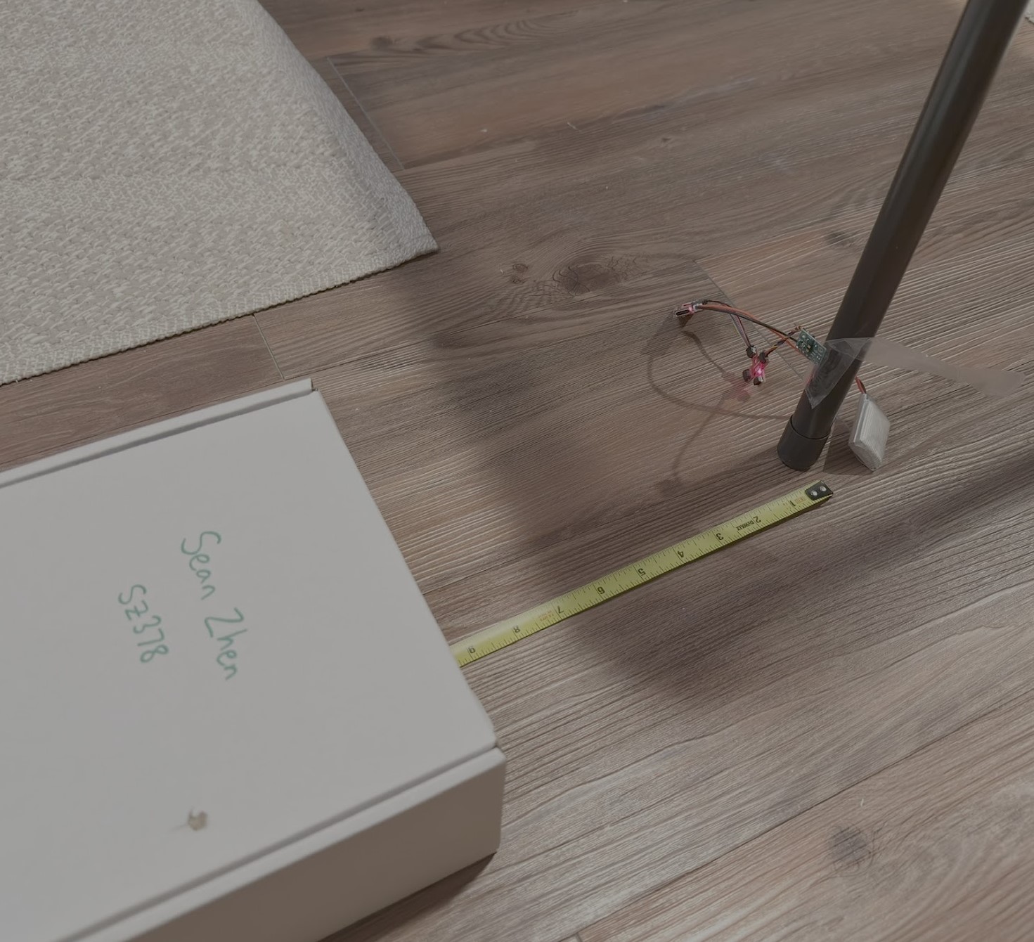
For this task, I taped my ToF sensor to a table leg and used the box as an object. Starting from 5 in, I moved the box in increments of 5 in away from the sensor and recorded the output distance from the sensor.
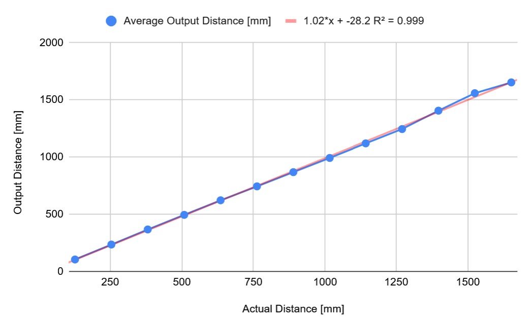
The sensor can accurately measure distance up to around 65-70 in (1.65 to 1.78 m), which is slightly greater than the specified maximum distance of 1.3 m for short mode. The output distance is linear in relation to the actual distance with a scale factor of 1.02. The average difference between actual and output distances is about 20 mm. The sensor appears to be accurate.
As I move the box further away from the ToF sensor, the readings appear to level off around 1750 mm. I believe that the sensor starts to detect the floor instead of the box, so an appropriate cutoff distance should be assigned for the robot to know that there is no object in front of the sensor. The ToF sensor should also be mounted high off the ground so it does not detect the floor as an object.
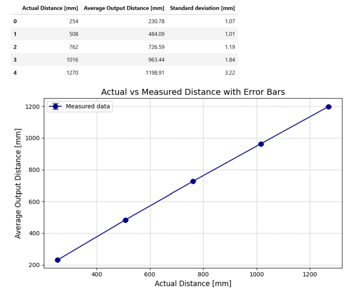
To test the repeatability, I recorded the average output distance and the standard deviation in mm from 10 to 50 inches (254 to 1270 mm) in 10 in (254 mm) increments. The standard deviation is around 1 mm for 10 to 30 in (254 to 762 mm), but increases as the actual distance increases.
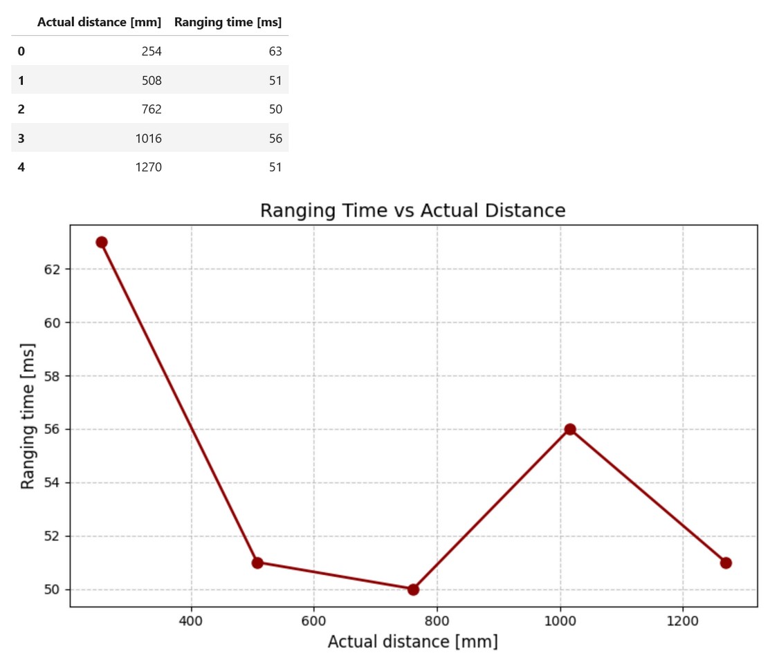
The above table and graph shows the ranging time in ms. This time represents the amount of time to receive a new time-stamped datapoint. This data was recorded using the same procedure as the repeatability data. The ranging time does not appear to be a function of the actual distance of the object from the sensor.
Task 8: Both ToF sensors
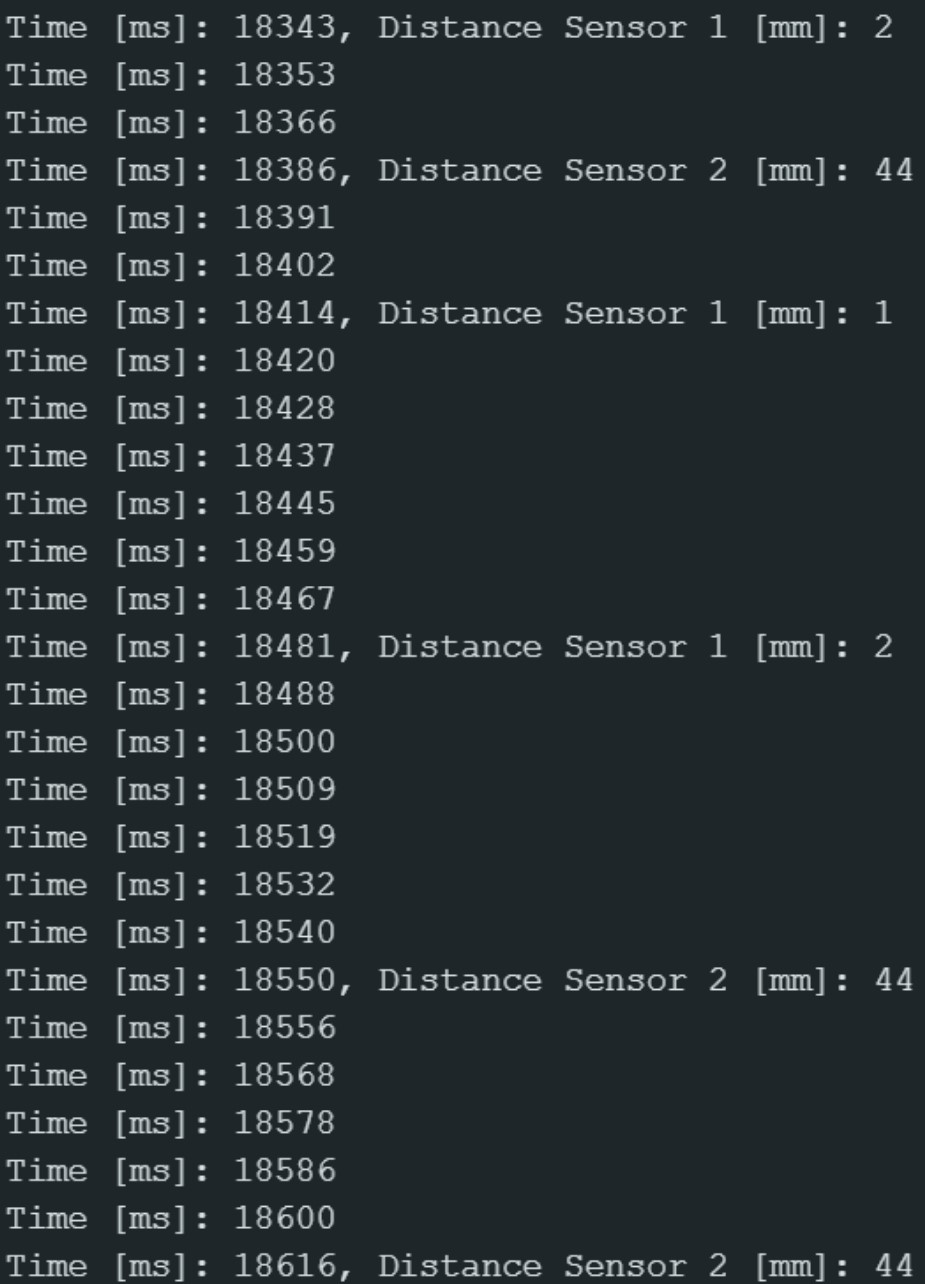
The above code uses Serial Monitor to simultaneously print the distances of the two ToF sensors. I used the shutdown pin to turn off sensor 1 so I can set an unique address for sensor 2. The video below shows both sensors working.
Task 9: ToF sensor speed
The loop executes every 8-15 ms. The time between updates for sensor 1 ranges from 43 to 67 ms while sensor 2 ranges from 66 to 164 ms. The limiting factor is how quickly the ToF sensors receive new data.
Task 10: Time-stamped ToF and IMU data
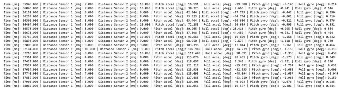
I collected the ToF and IMU data for 5 seconds and sent it over Bluetooth to my laptop. The image below shows the data received.
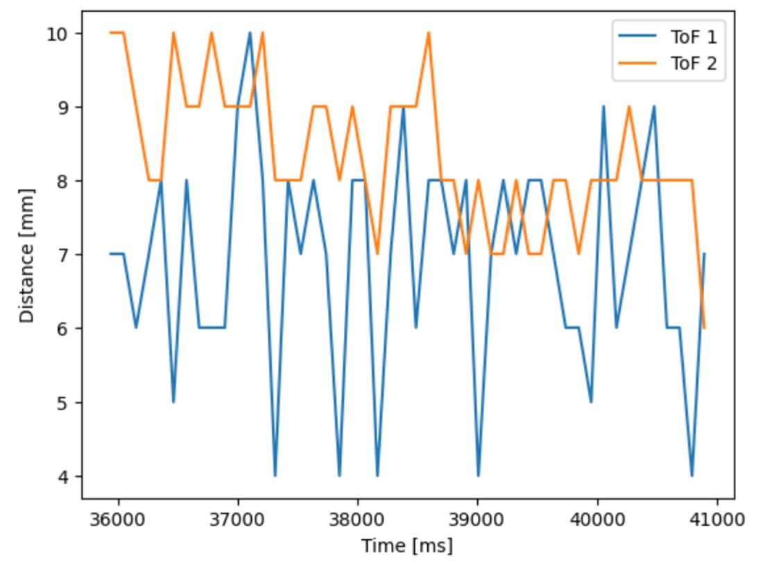
Task 11: Plot of ToF data against time
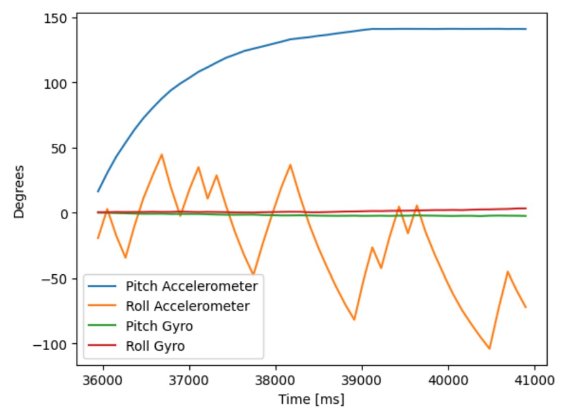
Task 12: Plot of IMU data against time
Additional Tasks for 5000-level students
One type of IR distance sensors is IR triangulation sensors. The IR emitter projects light towards an object and the light reflects off and hits the detector lens at a specific angle. The angle is used to determine the distance of the object. One pro is they are very accurate because they measure the angle of the returned light instead of the intensity. One con is they have a non-linear output and requires a calibration curve to determine the distance.
Another type of IR distance sensors is time of flight (ToF) sensors. The sensor emits a infrared laser and measures the time it takes for the light to travel to an object and back towards the sensor. One pro is that these sensors have very long range and can measure up to several meters. One con is that the output distance may vary depending on the type of surface.
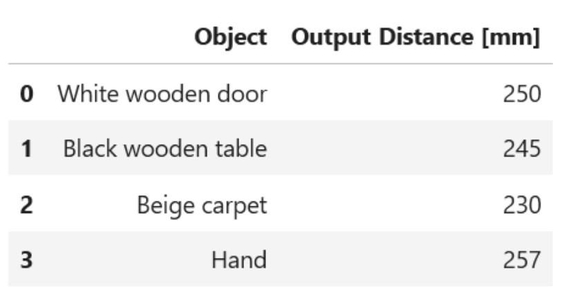
Each object was placed 254 mm (10 inches) away from the sensor. It appears that this ToF sensor is not sensitive to different colors as long as they are flat and matte (not reflective). The output distance varied the most from expected for the beige carpet. This may be caused by the uneven surface of the carpet.
Collaborators
I collaborated with Sam Zhen while working on this lab. I also used Aidan Derocher’s page as a reference.
Back to Labs