Lab 4
Prelab

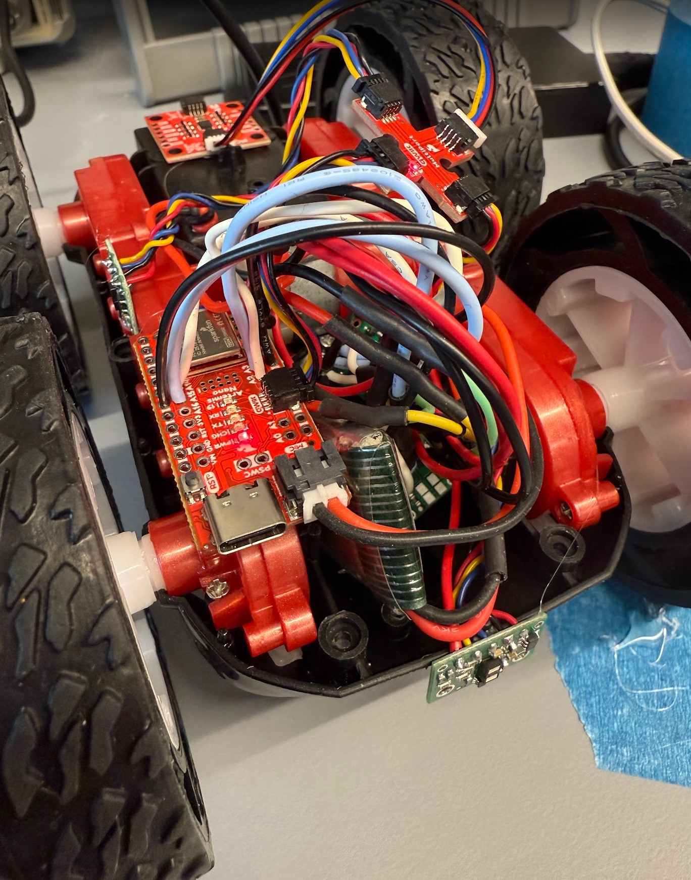
A 3.7V 850mAh battery is used to power the motor drivers. The leads of the battery are connected in parallel to the GND and VIN pins of both motor drivers. The analog pins must be PWM capable. For the first motor driver, AIN1 and BIN1 are connected together to A2 pin, and AIN2 and BIN2 are connected together to A3 pin. For the other motor driver, AIN1 and BIN1 are connected to A14 pin, and AIN2 and BIN2 are connected to A15 pin. The other GND pin on each driver must be connected to the common ground on the Artemis to ensure the signals are properly referenced. AOUT1 and BOUT1 are connected together to one lead on each motor, and AOUT2 and BOUT2 are connected together to the other lead.
The reason why we are using two different batteries to power the Artemis board and the motor drivers is to ensure that the Artemis board receives a stable power supply. If we were to use only one battery, the motor drivers can draw a lot of current and cause the voltage to drop. This voltage may drop below the operating voltage for the Artemis and cause it to turn off or not operate correctly.
Task 1: Connecting the first motor driver
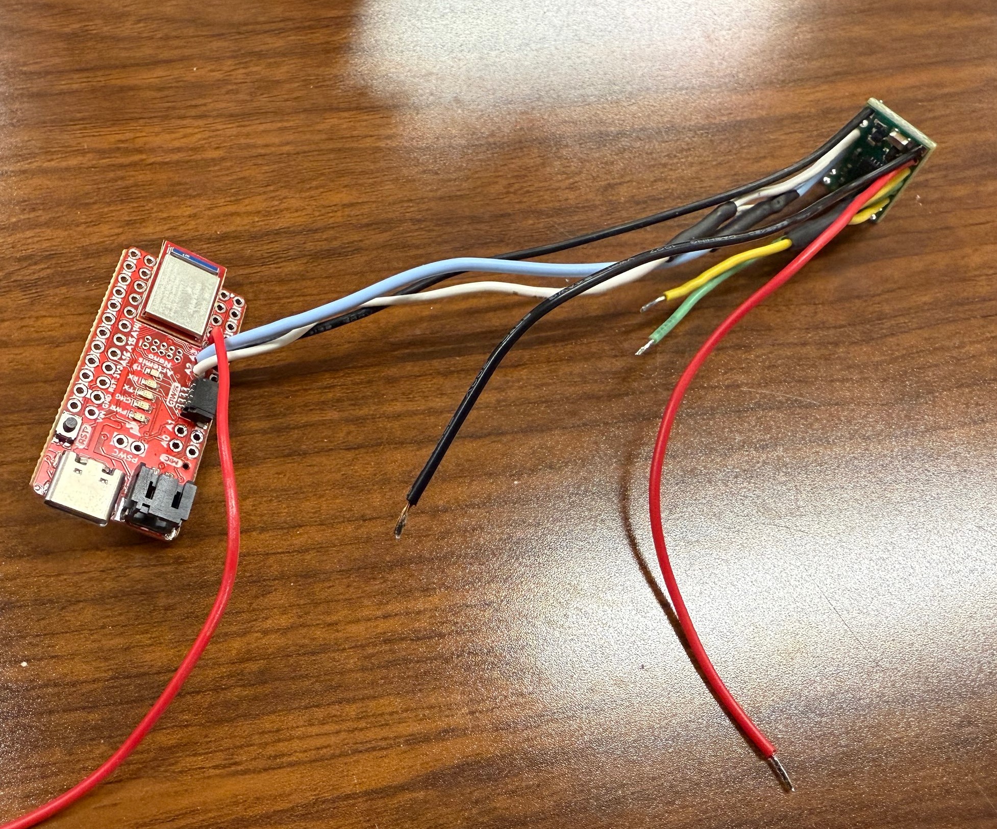
I first soldered the wires between AIN1 and BIN1 to the A2 pin, and AIN2 and BIN2 to the A3 pin. I connected a ground wire between the GND pin on the motor driver to the ground rail on the Artemis. I soldered yellow wires to connect AOUT1 and BOUT1 and green wires to connect AOUT2 and BOUT2. The green and yellow wires will connect to the oscilloscope. I then soldered black and red wires to GND and VIN pins. These two wires will connect to an external power supply.
Based on the data sheet for the motor drivers, the operating voltage is 2.7 - 10.8 V. Since the battery is 3.7V, we can safely set the power supply to 3.7V to power the motor driver. We can also increase the voltage as necessary if the driver draws a high current.
Task 2: Use analogWrite commands to generate PWM signals
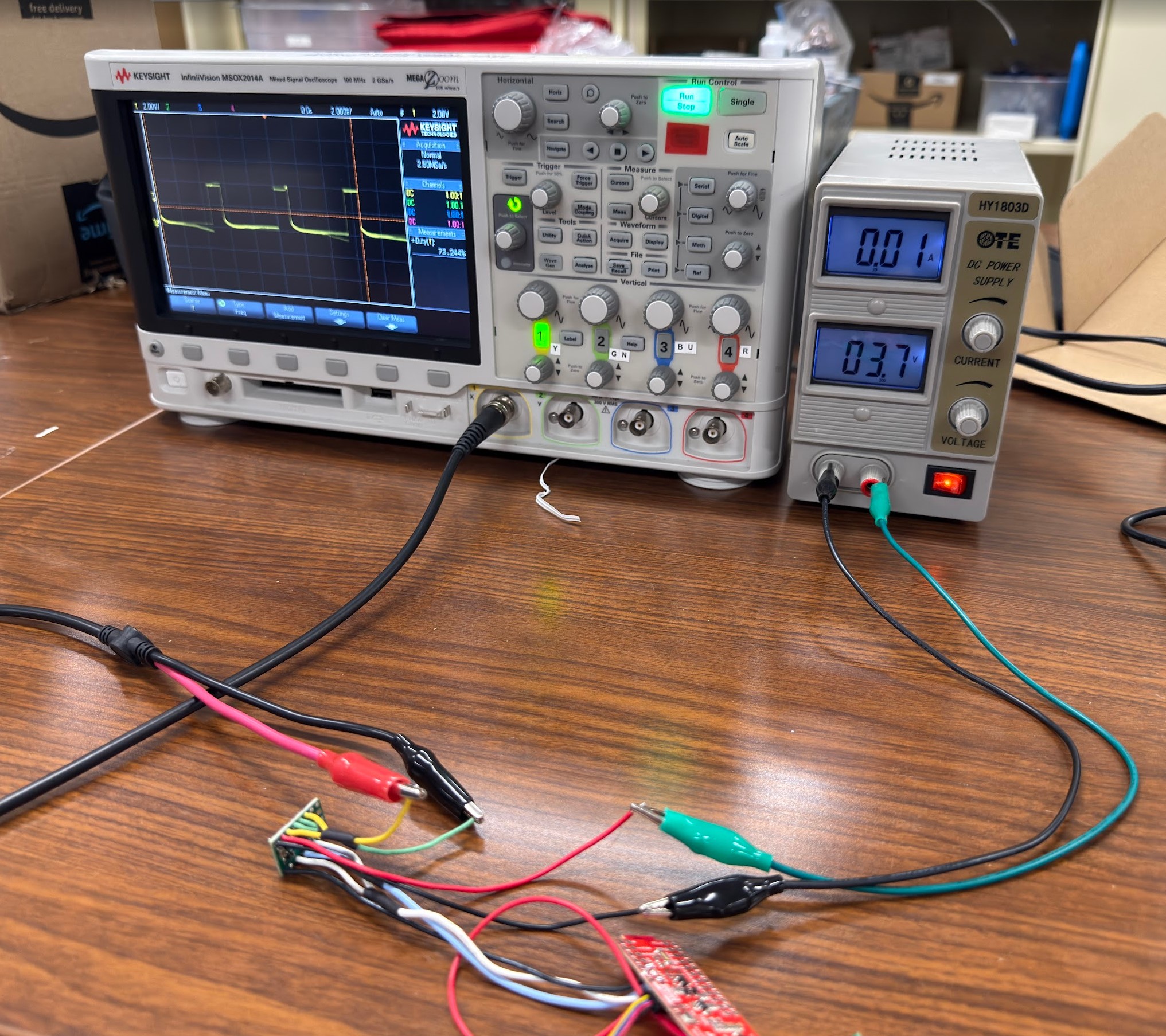
The yellow and green wires for the output signals of the motor driver are connected to the oscilloscope. The red and black wires for power input are connected to the power supply.
The following code snippet defines pin A2 as the pin we are setting to output. A PWM value of 0 is written to the pin to ensure the motor driver is not sending a signal during setup. I then sent a PWM value of 50 to the pin.
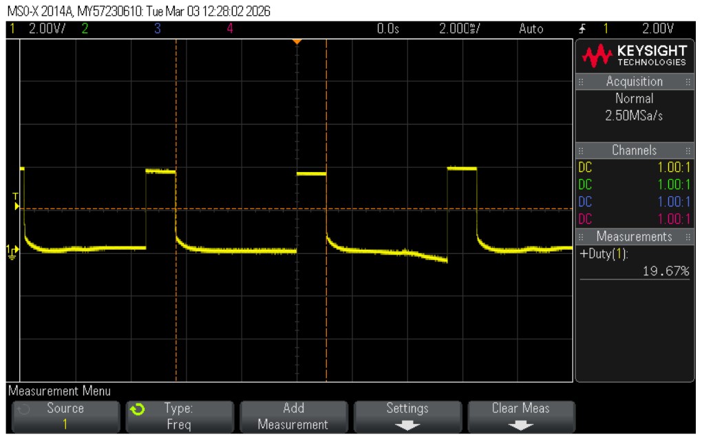
The screenshot of the oscilloscope shows that the signal has a duty cycle of 19.67%. The duty cycle is 100% at a PWM value of 255, so 50/255 = 19.61%. This duty cycle matches expectations.
Task 3: Take the car apart
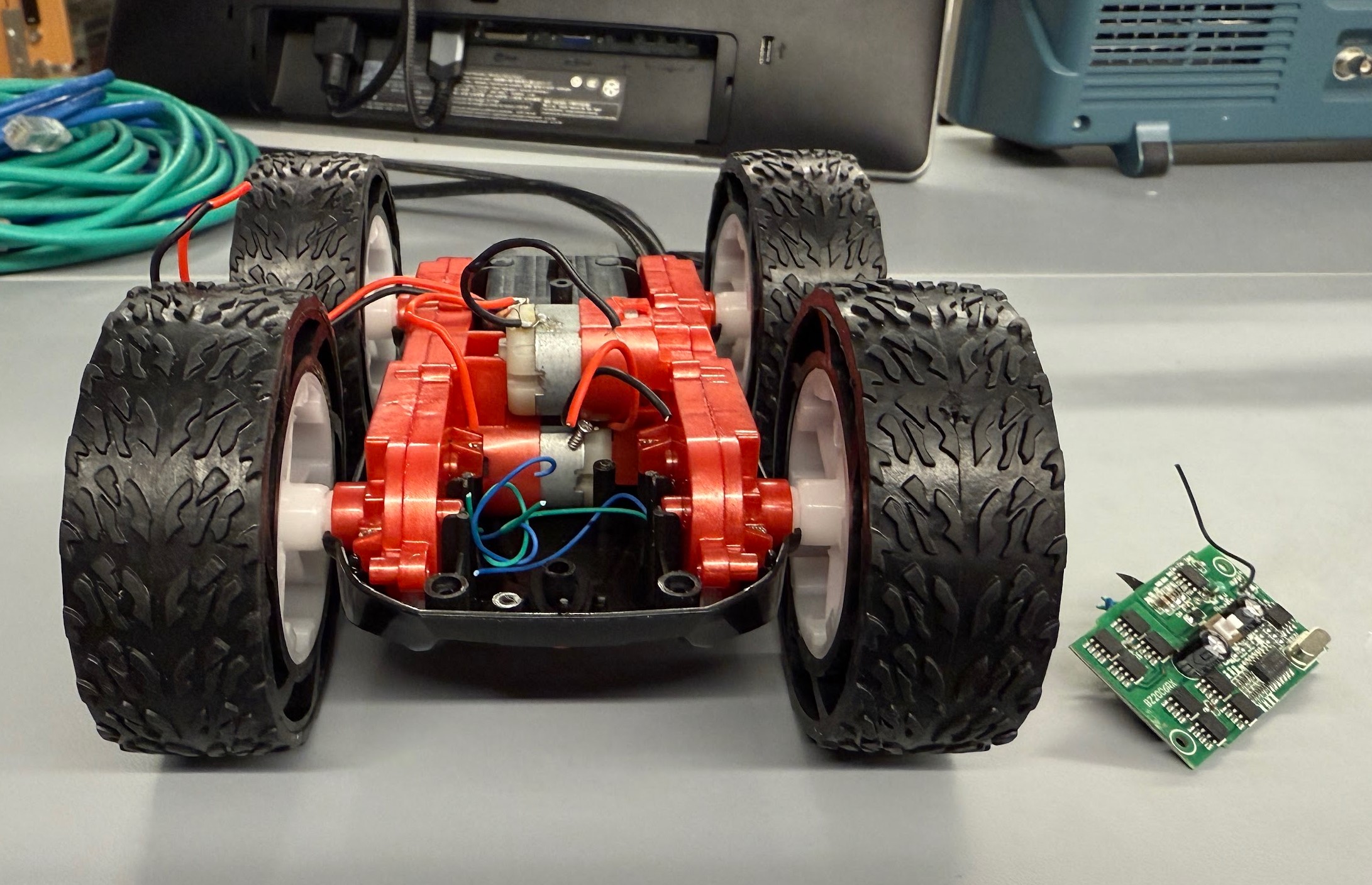
I cut the wires connecting the PCB board to the motors and removed it from the car.
Task 4: One side of wheels spinning
I created an infinite loop where the wheels spin forward for 3 seconds, stop for 3 seconds, backward for 3 second, and then stop for 3 seconds before repeating.
Using the same PWM duty cycle, I had to increase the voltage on the power supply to 5V to make the wheels spin properly. This is a safe voltage for the motor drivers.
Task 5: Power the motor driver with the battery
I will be using the existing battery connector in the car to connect the battery. I will make sure that the colors of the wires match before connecting it to the car. I used alligator clips to connect the battery to the motor driver because I need to wire the connector to both drivers later.
Task 6: Connect the second motor driver
Following the diagram presented in the prelab section, I wired the second motor driver and motor to the Artemis.
Task 7: Install everything onto car
I used hot glue to secure all of the components so they don’t shift when the car is driving. This ensures I can get reliable readings from the IMU and TOF sensors. One TOF sensor is mounted to the front of the car while the other one is mounted to the side between the wheels. The IMU is secured on top of the battery compartment. The Artemis board is mounted on one side near the wheels. The battery powering the Artemis along with the motor drivers are tucked in the space where the old PCB board used to be. The battery powering the motor drivers is in the battery compartment on the underside of the car.
Task 8: Lower limit PWM value
The lowest PWM value for the car to move forward is 50 to left motor and 110 to right motor. For on-axis turns, the left side is powered forward at 170 and the right side is powered backward at 200.
Task 9: Calibration
For the car to drive forward in a straight line, I recorded three sets of PWM values from slow to fast.
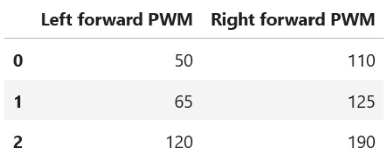
A linear regression line for this data is Right = 1.15 * Left + 51.3.
The following code snippet shows the implementation of this calibration factor.
To test if this calibration factor works, I tested a PWM value of 75. The video demonstrates that the car was able to follow a straight line for at least 6 feet.
Task 10: Open loop
Additional Tasks for 5000-level Students
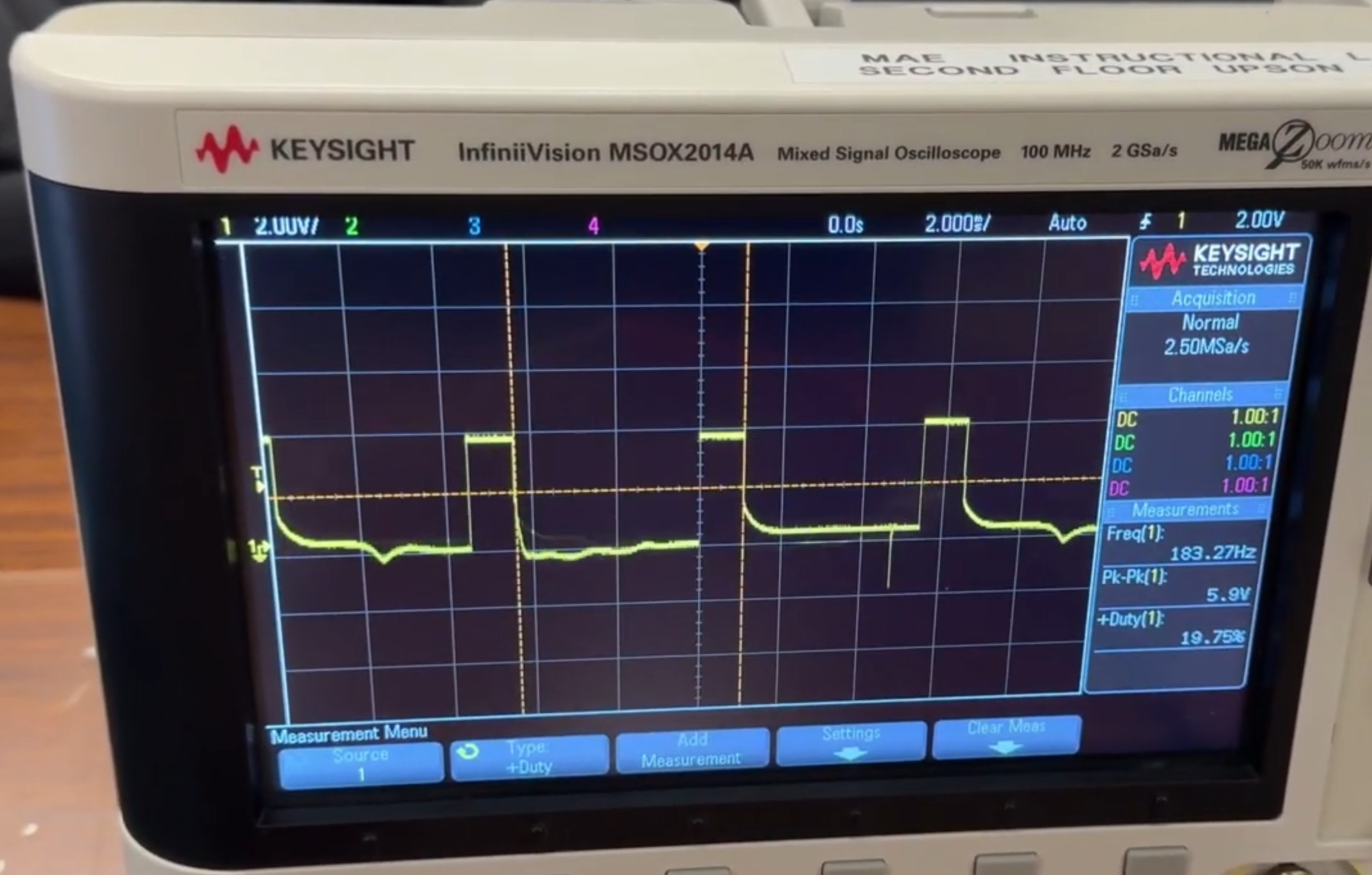
(1) When sending a PWM value of 50 to the motor driver, the oscilloscope shows that the frequency of this signal is around 183 Hz. This is done with this line of code: analogWrite(PWM_PIN_LEFT_1, 50);. This frequency is relatively slow for a PWM signal and can cause the motors to not run as smoothly. This can be seen in several of my videos where the car looks like it was very jittery when it was driving forward at low speeds. Manually configuring timers to generate a faster PWM signal allows the motors to run more smoothly, reduce audible noise from the motors, and provide a more consistent output to the motors.
(2) I used the values from Task 8 to overcome the static friction, and then I decreased the values when the robot was moving to see if it will continue to move. For moving forward, I used the values from Task 8 of 50 to left motor and 110 to right motor to start moving. Once it started moving, I was able to program 35 to the left motor and 95 to the right motor to keep it moving.
For on-axis turns, I used 170 to move left forward and 200 to move right backward to start moving. However, I was unable to find a value that was lower that kept the car turning. This shows that the car has a lot of friction when it is turning in place and requires a higher PWM value to start and continue turning.
Below is the code I used to test each case:
Collaborators
I collaborated with Sam Zhen while working on this lab. I also used Aidan Derocher’s page as a reference.
Back to Labs