Lab 6
Orientation Control
Prelab
Similarly to Lab 5, when I run my command, I will send values of Kp, Ki, and Kd to the Artemis over Bluetooth by writing these values in my command in my Jupyter notebook. An example of the command I would send is: ble.send_command(CMD.COMMAND_NAME, "1|2|3"). This allows me to fine tune my closed loop controller without having to upload new code whenever I make any changes.
In my Arduino code, I need to add this to the beginning of the case to receive the inputs:
I will implement a time out in my code so the robot automatically stops after a defined amount of time. I will send this time out value over Bluetooth as well. This time out will always run regardless of Bluetooth connection.
I will initialize arrays when I run the controller and send these arrays to my computer over Bluetooth when the program is finished. The data that I’m collecting in these arrays are timestamps, gyroscope readings, and outputs from the branches of the PID controller for debugging.
Lab Tasks
Before I calibrated the PI controller, I checked the minimum PWM value required to make the robot make an on-axis turn. The minimum for the left motor is 153, and the minimum for the right motor is 180. Based on these values, I created a calibration factor of pwm_left = 0.85 * pwm_right.
PID Input Signal
To calculate the yaw angle of the robot, I first initialized the yaw as 0 degrees. The equation to calculate the yaw is yaw = yaw + myICM.gyrZ() * dt, where dt is in seconds.
Digital integration of gyroscope data over time can cause the yaw reading to drift due to bias. Any drift in the gyroscope data can lead to large and growing error over time. For example, a bias of 0.1°/s causes an error of 6° after one minute. One way to minimize this problem is to have bias calibration by recording the gyro output when the robot is stationary and subtract the average readings from all subsequent readings.
Based on the graph of yaw readings below, the yaw reading slightly drifted to around 0.1 degrees after roughly one second. This would cause an error of ~6° after one minute.
The IMU datasheet states that the maximum rotational velocity that the gyroscope can read is 2000 degrees per second, which is 5.56 rotations per second. This is very sufficient for our robots. We can adjust the gyroscope sensitivity by changing the GYRO_FS_SEL parameter.
Derivative Term
It does not make sense to take the derivative of a signal that is already integrated. Differentiating the integrated signal would give the angular velocity, but this can come with additional noise. The best way to calculate the derivative term is to use the raw gyroscope measurement directly and simply multiply that reading by Kd.
A sudden change in the setpoint can cause a large jump in the error signal and cause a derivative kick if the derivative term acts on the error in the signal. If we calculate the derivative term from the raw gyroscope reading rather than error, this would eliminate the kick. A low pass filter is needed before the derivative term to remove the noise from the readings to make the derivative term more stable.
Programming Implementation
As mentioned in the prelab, I coded my command such that I can repeatedly send inputs to the Artemis over Bluetooth. This allows me to easily tune the PID terms without having to upload new code every time I need to change the values. In future applications of the PID controller, it will be necessary to change the setpoint in real time to make the robot drive at specific relative angles or approach at objects at certain distances.
It is possible to control the orientation while the robot is driving forward or backward. Based on the gyroscope readings and specific setpoint, we can calculate a rotational PWM value and simply add it to the translational PWM value for each motor. The orientation and translational PID loops would run separately and each PID loop would calculate its respective PWM values to input to the motors.
PI Controller
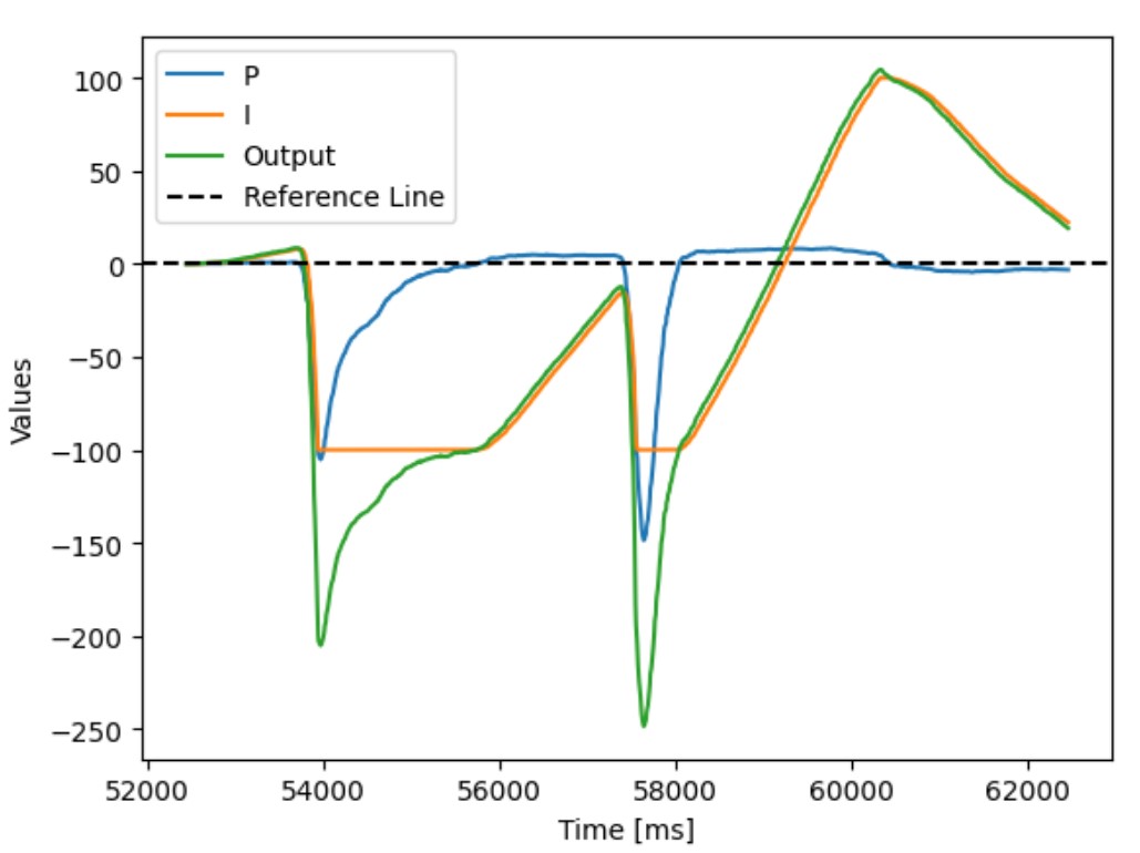
The final values for my PI controller is Kp = 4, Ki = 50. I decided not to include a derivative term in my controller because the friction in the motors and gearboxes provide enough of a damping force such that the robot does not oscillate around its setpoint and the overshoot is minimal. The integral term is very high because of the large PWM values necessary to overcome the static friction in the motors. The integral term needs to react quickly for accumulating error between the gyroscope yaw reading and the setpoint.
Below is the full implementation of the PI controller:
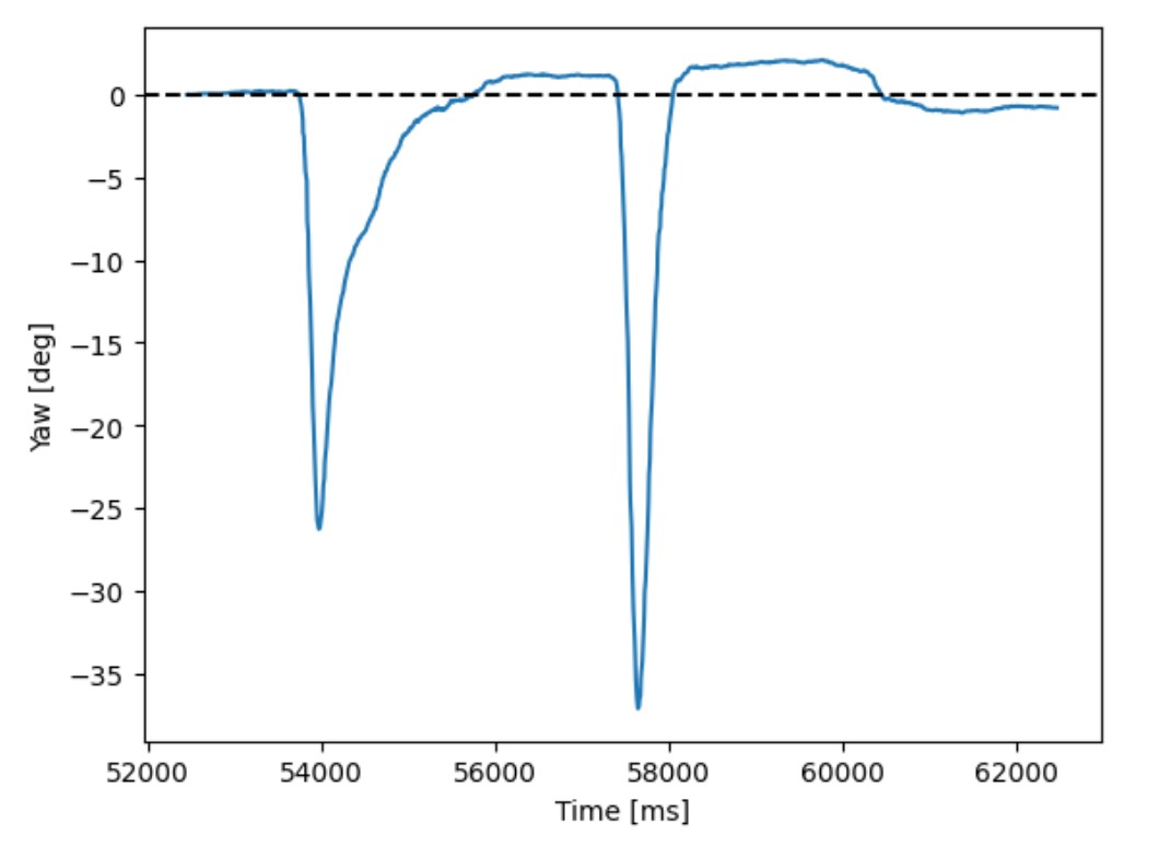
I pushed the robot two times and the robot was able to maintain its starting heading within 1 degree. The integral term was useful to make the robot make small adjustments due to accumulating error when the Kp term alone was not able to turn the robot.
Sampling Time
With a timeout value of 10 seconds, the robot recorded 1123 datapoints. This corresponds to a sampling frequency of 112.3 Hz, which is very quick for the PI controller to make small changes to the heading control.
Tasks for 5000-level students
Similarly to Lab 5, I implemented wind-up protection for the integrator. This is necessary because the total error accumulates and continues to increase when the error remains positive. This can cause the integrator term to be excessively large and can dominate over the Kp and Kd terms. To prevent the integrator term from over-saturating the controller, I clamped the integrator term if it exceeded the value of 130. This limits the integrator term to contributing a maximum of ~51% speed to the controller. This value was found through experimental testing.
Collaborators
I collaborated with Sam Zhen while working on this lab.
Back to Labs