Lab 9
Mapping
Control
I chose Method 2: PID control on orientation using integrated gyroscope readings to create the map.
I made my robot turn in 20 degree increments for a total of 18 readings per 360 degree rotation.
I plotted the values from my PID controller and the robot’s yaw readings to make sure my closed-loop control was making accurate 20 degree turns. I run the PID loop for 3 seconds for each 20 degree turn. It takes about 1 minute for the robot to complete a full 360 degrees.
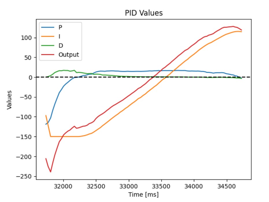
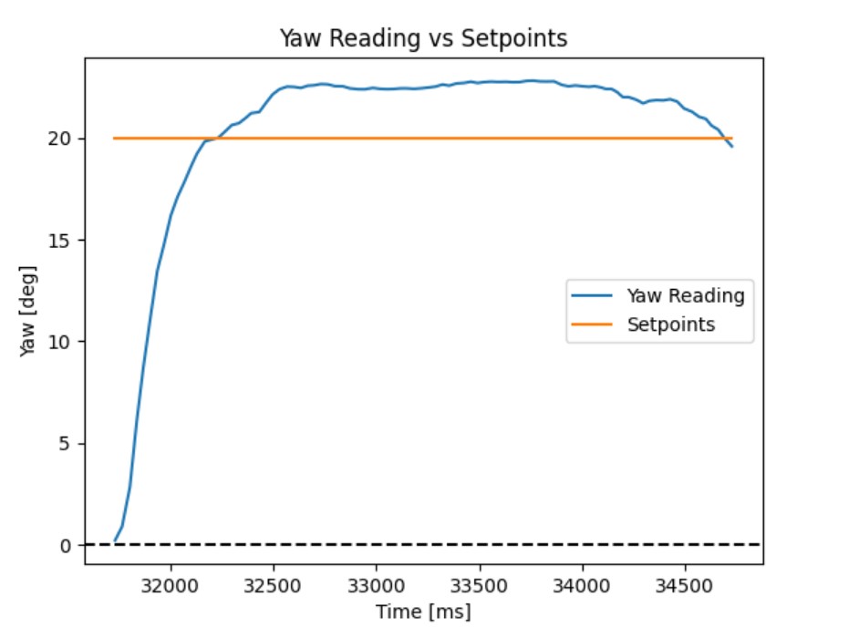
The graph below shows the yaw readings throughout the entire 360 degree turn and how quickly the robot reaches each new setpoint.
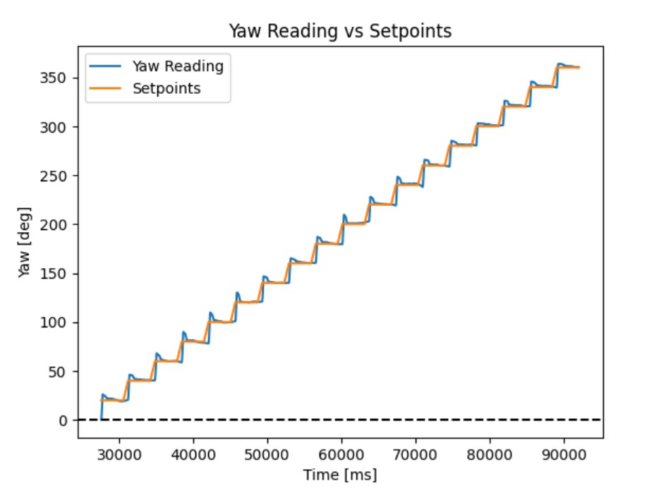
After each turn, the robot stops and records the distance reading from the TOF sensor. A stationary robot ensures that the TOF sensor is pointing towards a fixed point and provides a reliable reading.
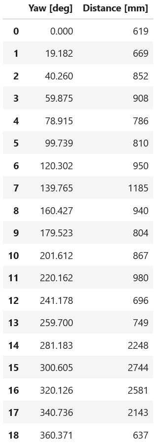
The table below shows the yaw and distance readings from the robot after it completed the 360 degree turn for the position (-3, -2).
The video below shows the robot completing a 360 degree turn.
Below is an truncated version of my code:
Estimating error of the map
The robot does not make a perfect on-axis turn. At any point during the turn, the robot could be 2 inches off from the starting location. The table above shows that the yaw reading can be up to 2 degrees off from the desired setpoint. From previous labs, the gyroscope has a small drift of 0.1 degrees per second, which can add up to 6 degrees of error after one minute.
The error in the map is caused by the robot’s translational offset and orientation error. Since the robot takes about 1 minute to complete a full 360 degree turn, the worst-case orientation error is 8 degrees by the end of the turn. If the robot makes a perfect on-axis turn and is facing the wall at a perfect 90 degree angle, the reading from the TOF sensor should be around 2 meters. However, if the robot is off by a maximum of 8 degrees, the reading may read (2 m)/(cos 8°) = 2.0197 meters. Adding on the maximum translation offset of 0.0508 meters (2 inches), the maximum error at the end of the turn is (2.0197 + 0.0508) - 2 = 0.0705 meters.
For average error, the orientation error grows linearly from 2° to 8° over the turn, averaging 5°. The average distance from the center to a wall over all directions for a 4×4 m square is about 2.244 m. The orientation error can cause an average error of (2.244 m)/(cos 5°) - 2.244 m = 0.0086 m. The average translation offset magnitude for a uniform distribution within a 2‑inch radius is (2/3) × 0.0508 m = 0.0339 m. Combining these errors gives an average error of 0.0086 + 0.0339 = 0.0425 m.
The map of a 4x4m room is expected to have an average error of 4.25 cm and a maximum error of 7.05 cm.
Read out Distances
I placed the robot and collected distance sensor readings on the 5 marked positions in the lab space: (-3,-2), (0,0), (0,3), (5,3), and (5,-3). I started the robot in the same orientation facing in the +y direction for all scans. Since the robot’s orientation can be up to 2 degrees off from the desired yaw angle, I cannot assume that the readings are equally spaced, so I will be using the gyroscope values when creating the map.
Below is the data I collected for all 5 positions:
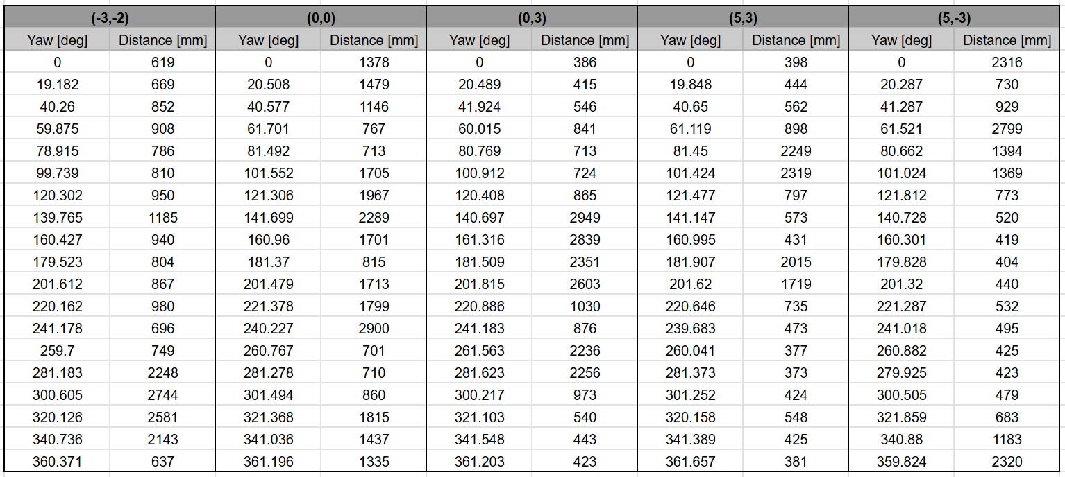
Below are the polar plots of each position, assuming that the robot is rotating in place:
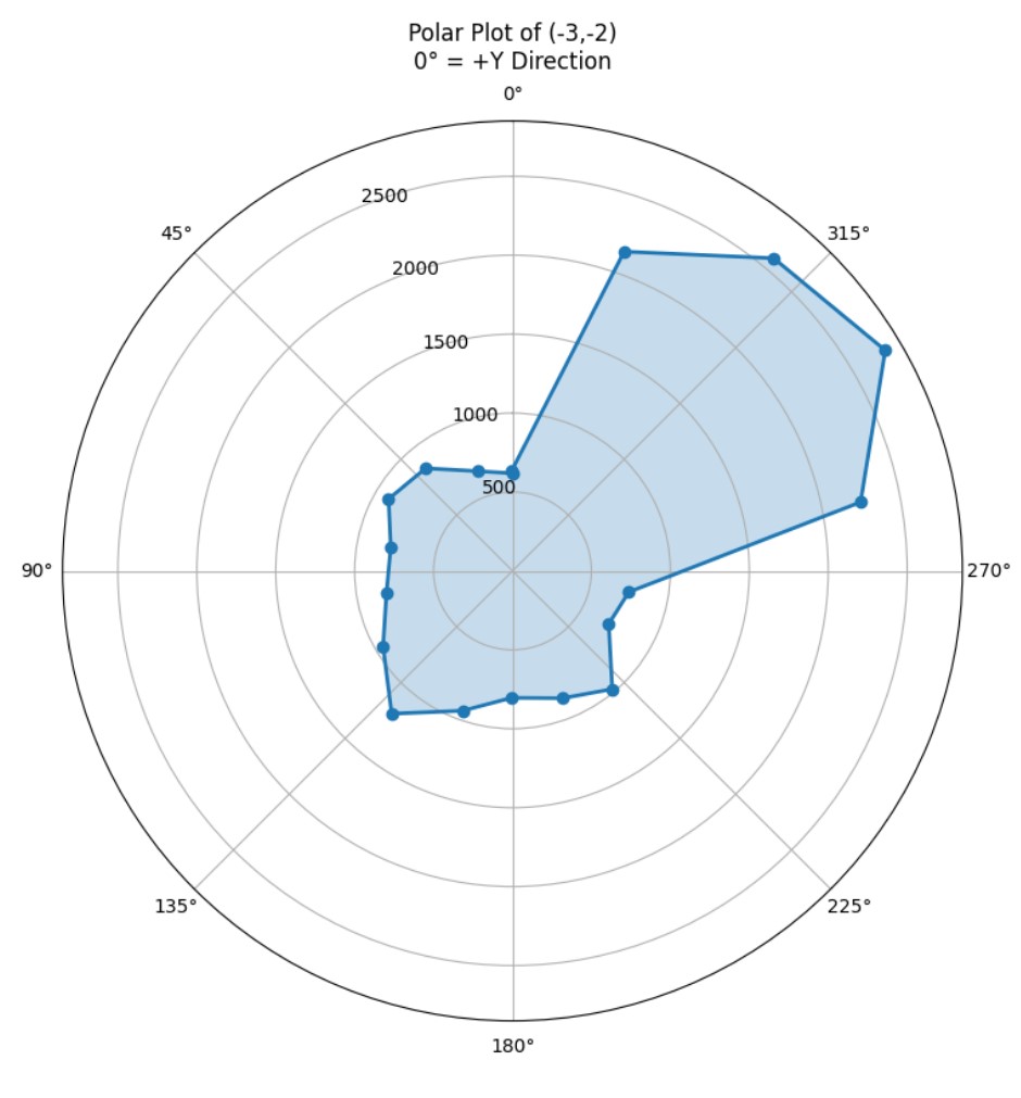
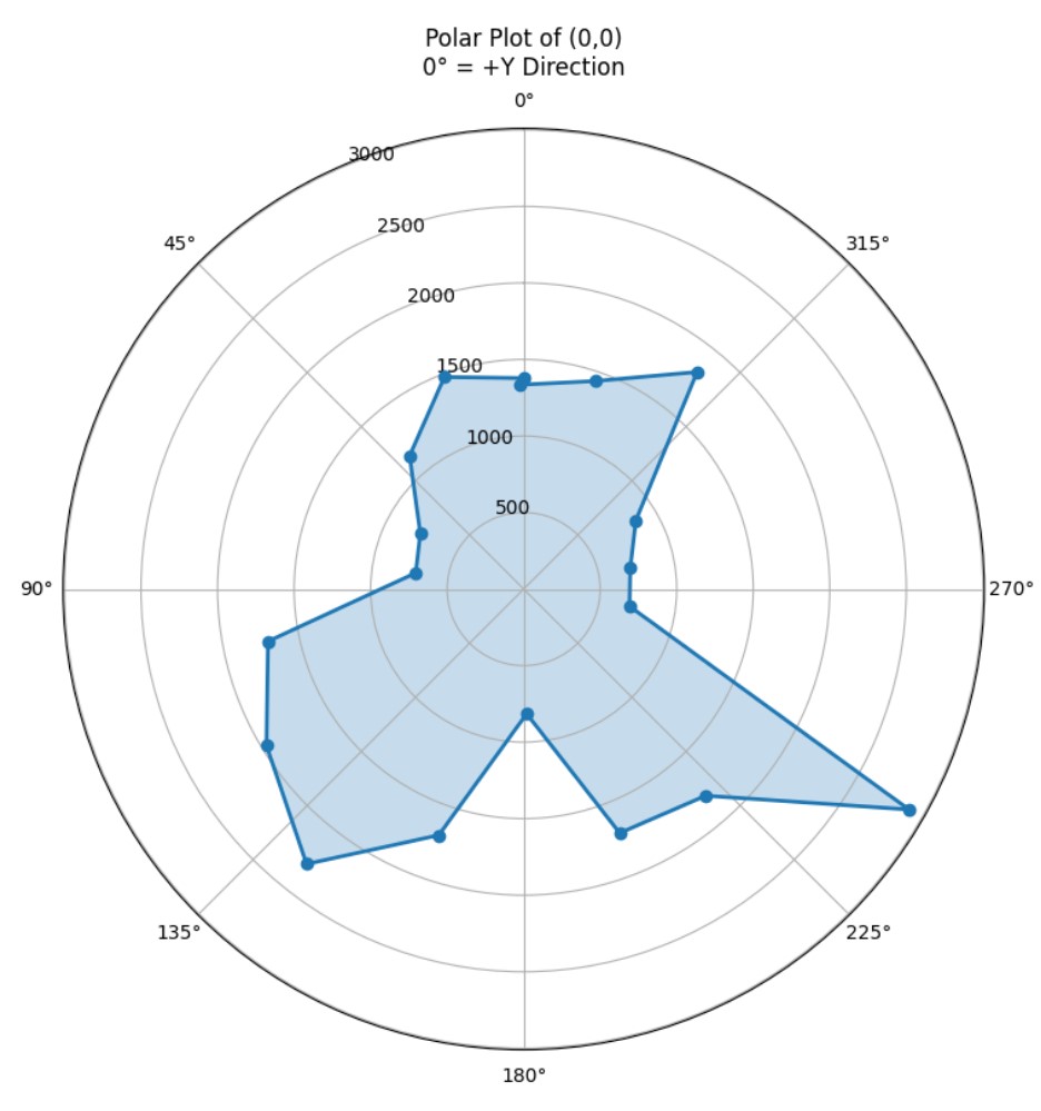
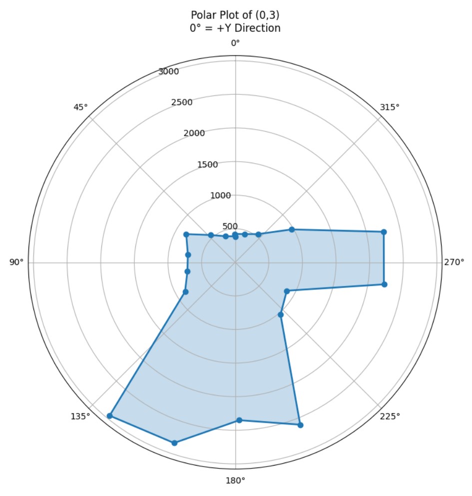
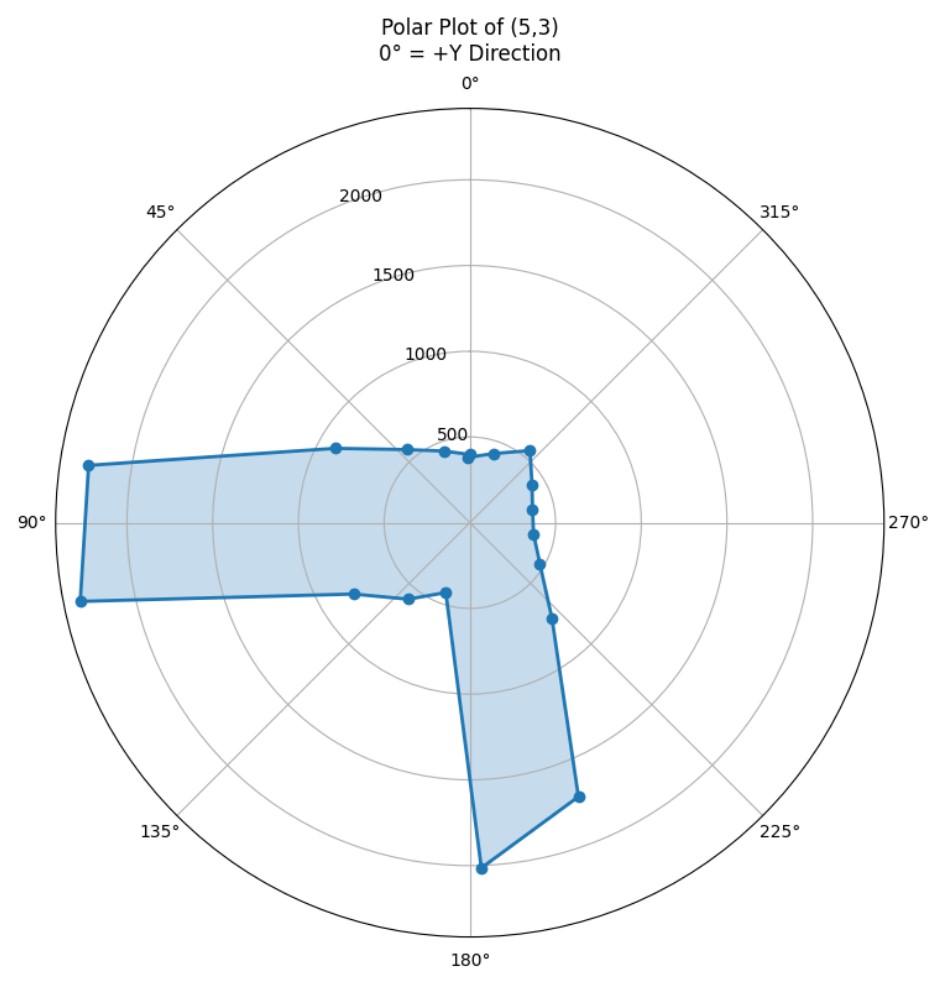

The measurements match up with what I expect. For each polar plot, it is very clear where the closest walls are relative to the position of the robot.
Below is the polar plot of (-3,-2) of two separate 360 degree turns.
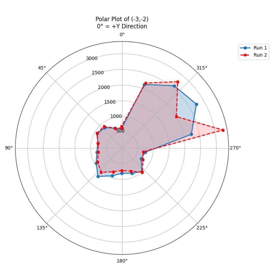
The distance sensor readings between the two runs are very close for the walls nearest the robot. The biggest difference between the two runs are the distance readings when the yaw is 280 and 300 degrees. The smaller distance readings are more reliable than the readings of large values. When creating the map, I will rely more on the close readings instead.
Merge and Plot your Readings
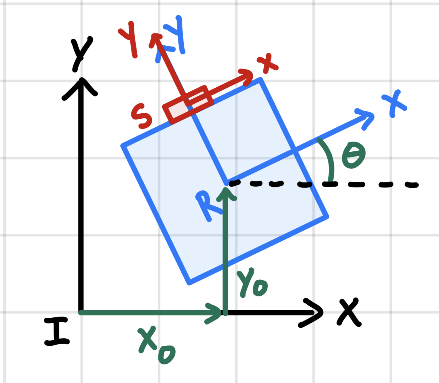
The three coordinate frames are:
- Inertial frame (room) - fixed to the room and centered at (0,0).
- Robot frame - attached to the robot center. X points to the robot’s right, Y points forward (direction of heading).
- Sensor frame - attached to the TOF sensor. The sensor is mounted at the front, centered, and facing forward. Its origin is 83 mm ahead of the robot center along the robot’s y-axis. The sensor’s axes are aligned with the robot frame (no rotation).
Theta represents the robot’s yaw angle with respect to the inertial frame. x_0 and y_0 represent the robot’s position relative to the origin of the inertial frame. d_m is the raw distance measured by the TOF sensor.
T_R^I matrix represents the transformation matrix from the robot frame to the inertia frame. T_TOF^R matrix represents the transformation matrix from the sensor frame to the robot frame. P^TOF is the distance sensor readings in matrix form. P^I represents the coordinates of the walls in the inertial frame.
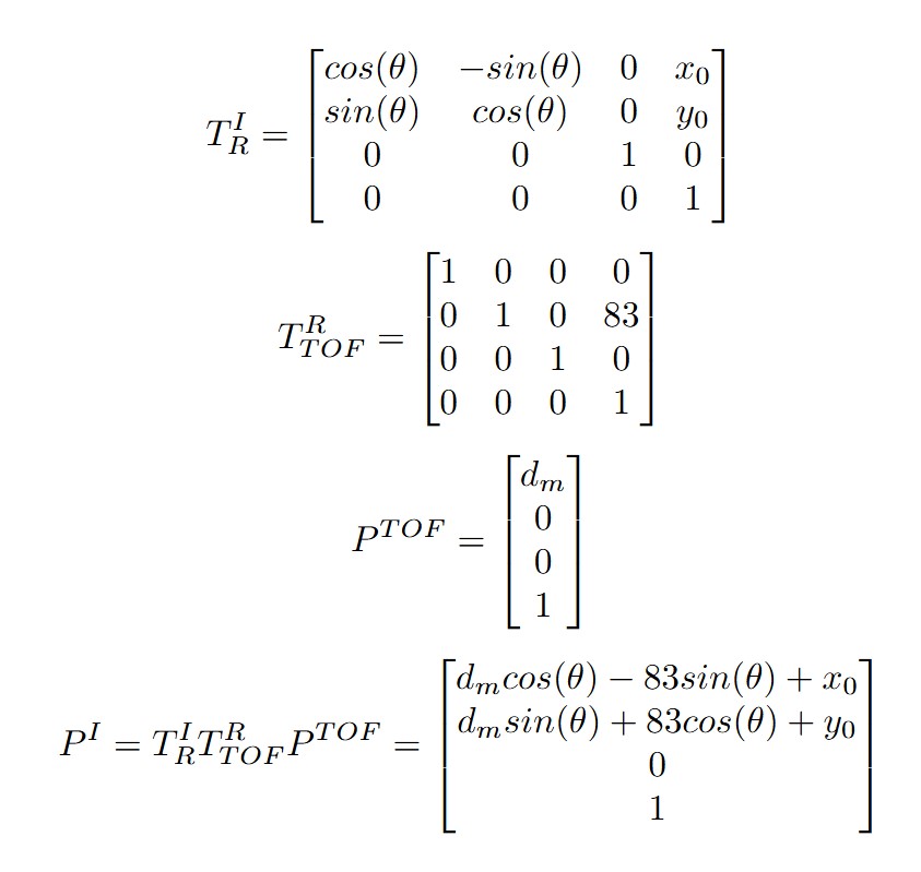
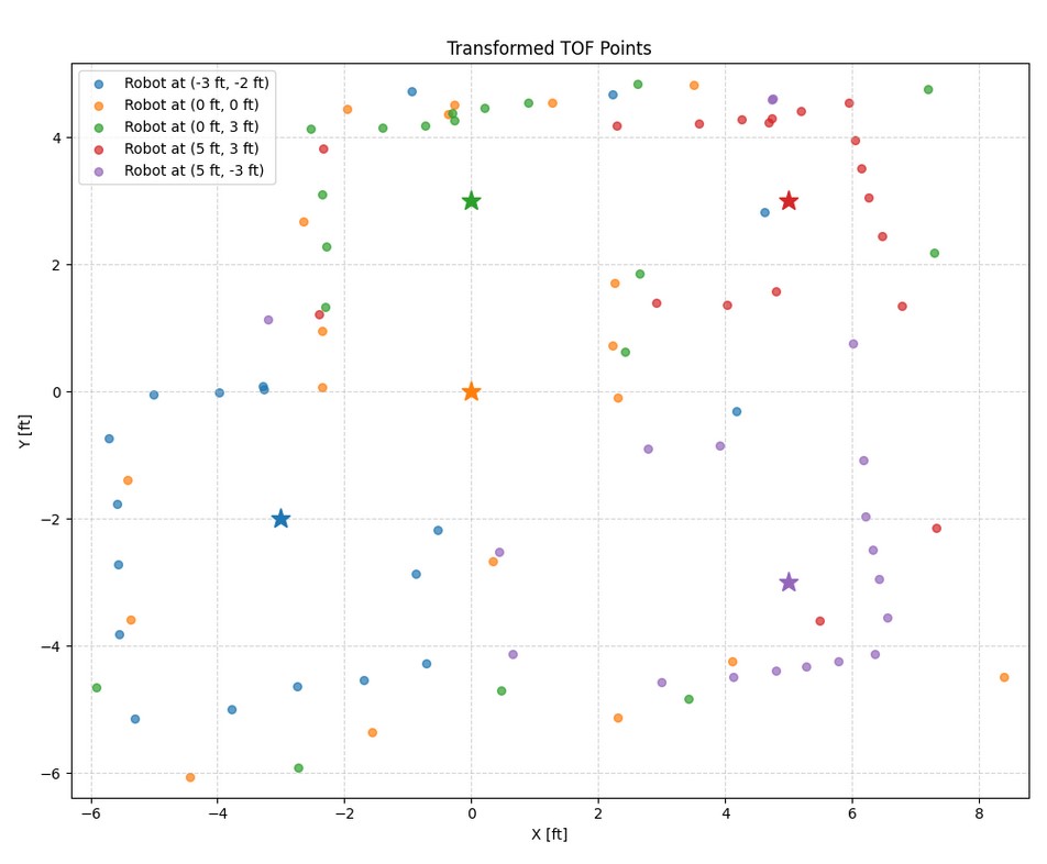
I wrote a function to convert the measurements from the distance sensor to the inertial frame of the room based on the robot’s yaw reading and position on the map:
Convert to Line-Based Map
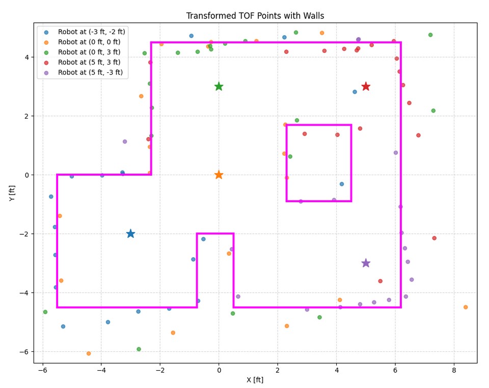
There are some points that are beyond the walls, but those points are associated with large sensor readings, which tend to be unreliable at large distances. Some of the close readings make a wall that is not perpendicular to other walls, but that can be caused by the robot not making a perfect on-axis turn.
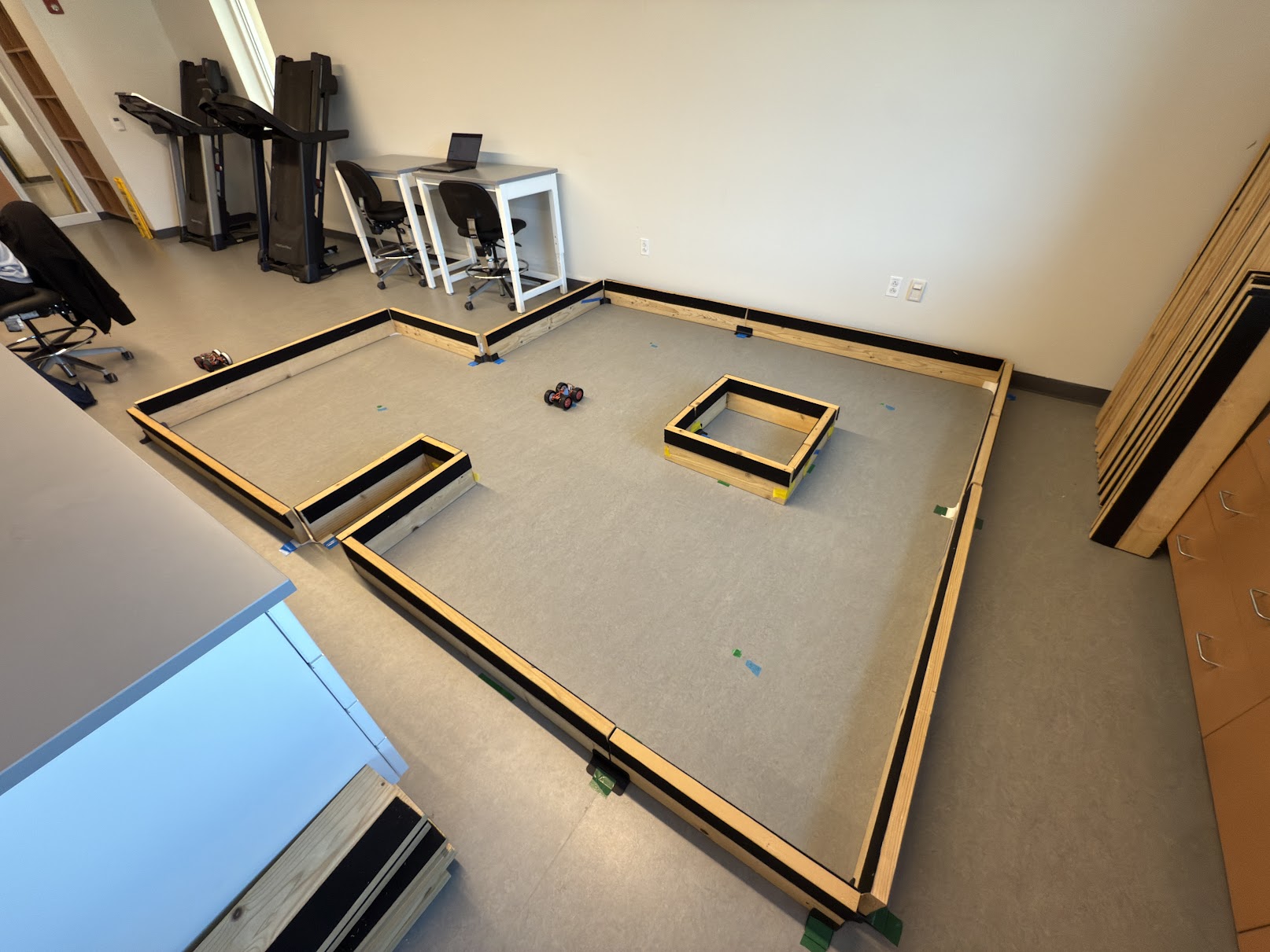
Below is a photo of the “world” for reference:
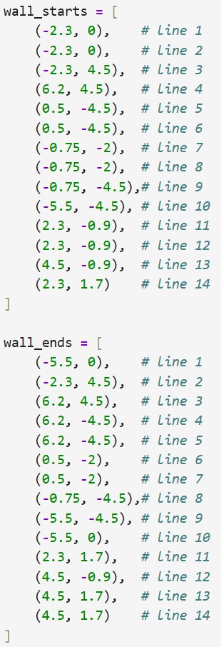
Below are the two lists containing the start and end points of the lines:
Collaborators
I collaborated with Sam Zhen while working on this lab.
Back to Labs